Transmission line tower ground resistance testing system and method based on two-pole method

A technology for grounding resistance testing and power transmission lines, applied in the high-voltage field, can solve the problems of inconvenient testing, low accuracy, and weak anti-interference ability, and achieve the effects of convenient layout, high accuracy, and strong anti-interference ability.

Inactive Publication Date: 2016-01-27
SICHUAN SUNLIGHT INTELLIGENT ELECTRIC EQUIP CO LTD
View PDF3 Cites 0 Cited by
  • Summary
  • Abstract
  • Description
  • Claims
  • Application Information

AI Technical Summary

Problems solved by technology

This method requires auxiliary laying of current electrodes and voltage electrodes, and the layout position and self-resistance of the auxiliary electrodes have a great influence on the test results; some tower locations may not have the space for arranging auxiliary ground electrodes, resulting in the failure of the test; a large number of tests must be carried during the test Lines and related tools, low efficiency, inconvenient testing
The latter representative instrument is the clamp meter. The clamp meter method uses the nearby pole tower as the loop, and tests the loop resistance through the induced current. This method is convenient for testing and is used in some practical applications, but this method is less affected by the connection mode of the lightning conductor. Large, and weak anti-interference ability, the accuracy is low in practical applications

Method used


Image

  • Transmission line tower ground resistance testing system and method based on two-pole method
  • Transmission line tower ground resistance testing system and method based on two-pole method

Examples


Embodiment Construction

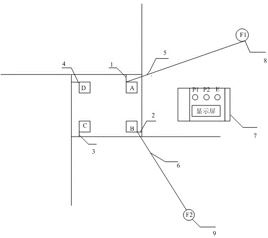
[0033] Describe technical scheme of the present invention in further detail below in conjunction with accompanying drawing: as figure 1 As shown, the grounding body of the transmission line includes four tower feet A, B, C, and D, respectively through the tower foot A and the ground network connection line 1, the tower foot B and the ground network connection line 2, and the tower foot C and the ground network connection line 3. The tower foot D is connected to the ground grid connection line 4 and the ground grid, and the auxiliary electrode F18 and the auxiliary electrode F29 are respectively connected to the tower foot through the ground lead I5 and the ground lead II6.

[0034] The test steps are described by testing the grounding resistance of tower foot A:

[0035] In the non-beta stage:

[0036] Auxiliary electrode F18 and auxiliary electrode F29 are buried 10 meters outside the grounding grid of the tower in advance, and the grounding lead I5 and grounding lead II6 ar...


PUM


Abstract

The invention discloses a transmission line tower ground resistance testing system and method based on a two-pole method. The system comprises a tower to be tested, and a plurality of tower legs are arranged at the bottom of the tower to be tested. The system is characterized in that an auxiliary pole F1 (8), an auxiliary pole F2 (9) and a ground resistance testing device (7) are further included; the auxiliary pole F1 (8) and the auxiliary pole F2 (9) are buried outside a tower grounding grid; in the measuring process, the auxiliary pole F1 (8) and the auxiliary pole F2 (9) are connected with a voltage feedback port P1 and a voltage feedback port P2 of the ground resistance testing device (7) through ground leads respectively, and a grounding grid connecting line of the tower legs to be tested is connected to a current output port E of the ground resistance testing device (7). According to the transmission line tower ground resistance testing system and method, carrying is convenient, line paying off is avoided, limit of the use range is avoided, and the problem that in the prior art, a measuring result is prone to interference is solved.

Description

technical field [0001] The invention relates to the field of high-voltage technology, in particular to a system and method for testing the grounding resistance of transmission line poles and towers based on the two-pole method. Background technique [0002] The grounding of transmission line poles and towers is very important to the safe and stable operation of the power system. Poor grounding of poles and towers will cause lightning accidents and cause line tripping. Grounding resistance measurement is a necessary means to check whether the grounding device meets the requirements of the regulations. Accurate measurement of grounding resistance can verify whether the design of the grounding system is reasonable, detect changes or defects in the grounding system in time, and avoid economic losses or accidents that may be caused by unqualified grounding. In order to ensure that the grounding resistance meets the design requirements, the "Operation Regulations for Overhead Pow...

Claims


Application Information

Patent Timeline
IPC IPC(8): G01R27/20
Inventor 苏凡凡余旭东
Owner SICHUAN SUNLIGHT INTELLIGENT ELECTRIC EQUIP CO LTD
Why Eureka
Try Eureka