
Method for calculating maximum circumferential stress of annular valve plate with different thicknesses of hydro-pneumatic spring

A technology of circumferential stress and oil-gas springs, applied in the field of oil-gas springs, can solve problems such as unsatisfactory and lack of analytical calculation formulas

Active Publication Date: 2016-01-27
SHANDONG UNIV OF TECH
View PDF5 Cites 3 Cited by
  • Summary
  • Abstract
  • Description
  • Claims
  • Application Information

AI Technical Summary

Problems solved by technology

With the rapid development of the automobile industry and the continuous improvement of driving speed, higher requirements are put forward for the design of oil-gas springs and unequal-thickness annular valve plates. Currently, the maximum circumferential stress is calculated by solid modeling using finite element simulation software. Simulation check calculation lacks accurate analytical calculation formulas, which cannot meet the requirements of the rapid development of the modern automobile industry and the modern CAD design of oil and gas springs

Method used


Image

  • Method for calculating maximum circumferential stress of annular valve plate with different thicknesses of hydro-pneumatic spring
  • Method for calculating maximum circumferential stress of annular valve plate with different thicknesses of hydro-pneumatic spring
  • Method for calculating maximum circumferential stress of annular valve plate with different thicknesses of hydro-pneumatic spring

Examples


Embodiment Construction

[0026] specific implementation plan

[0027] The present invention will be further described in detail through an embodiment below.

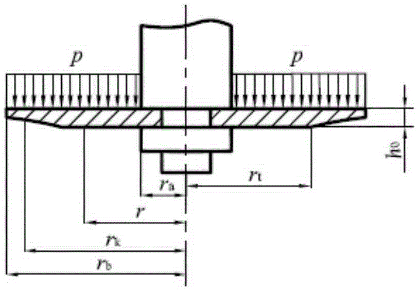
[0028] The oil and gas spring of a special vehicle adopts annular valve discs of unequal thickness, the elastic modulus E = 200GPa, Poisson's ratio μ = 1 / 3, and the thickness of the equal thickness part is h 0 =0.3mm, variable thickness radius r t =7.3mm, effective inner circle radius r a =5.0mm, outer circle radius r b =8.5mm, the uniform pressure received is p=3.0MPa.

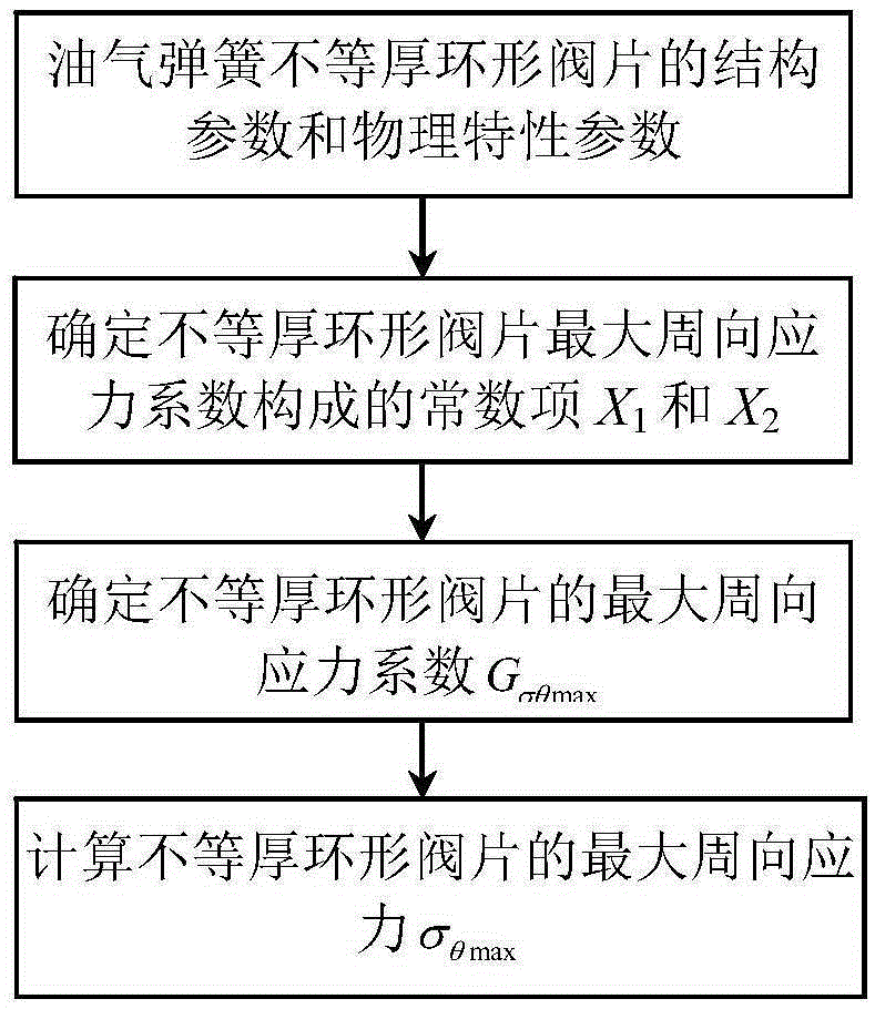
[0029] The calculation method of the maximum circumferential stress of the oil-gas spring unequal thickness annular valve plate provided by the example of the present invention, its calculation flow chart is as follows figure 1 As shown, the mechanical model of the oil-gas spring unequal-thickness annular valve plate is as follows figure 2 As shown, the specific steps are as follows:

[0030] (1) Determine the constant term X formed by the maximum circumferential stress ...


PUM


Abstract

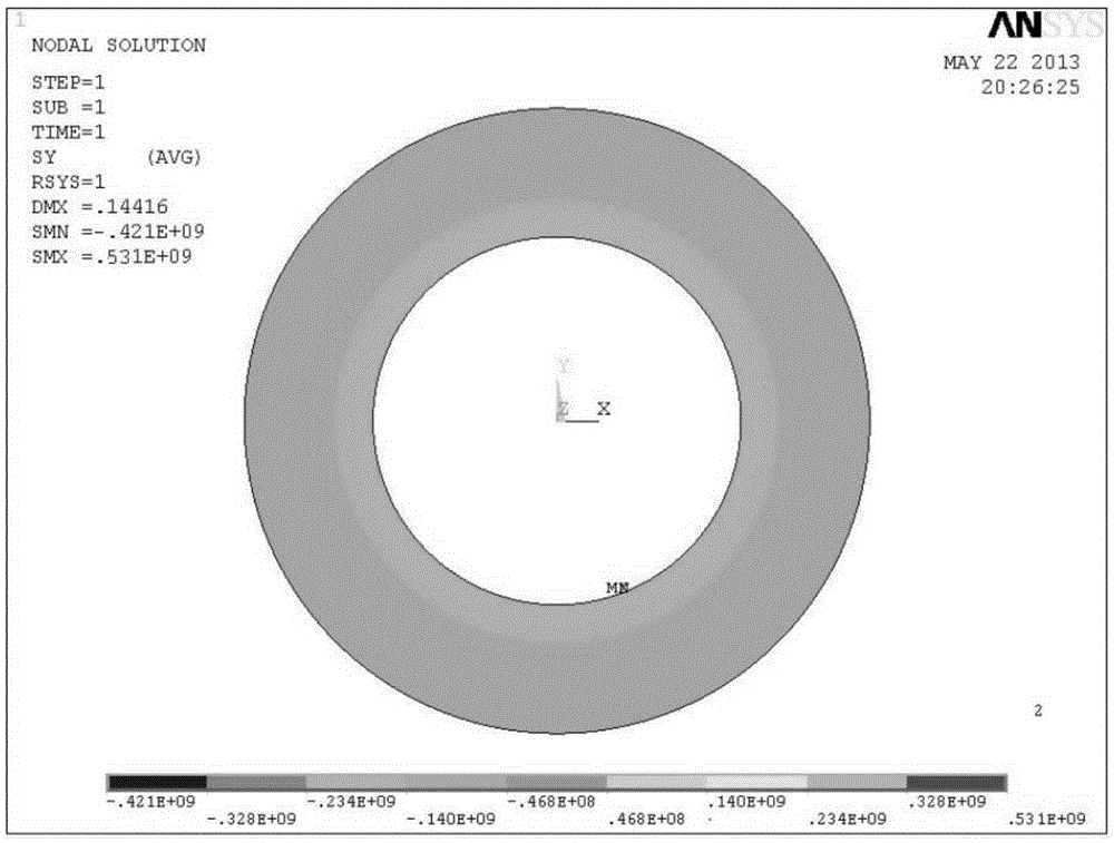
This invention relates to a method for calculating maximum circumferential stress of an annular valve plate with different thicknesses of a hydro-pneumatic spring, and belongs to the technical field of hydro-pneumatic suspension. The method solves the problem that the methods for calculating the maximum circumferential stress of the annular valve plate with different thicknesses of the hydro-pneumatic spring are not reliable in the prior art, and mostly a finite element software is used for simulating the maximum circumferential stress of a given pressure so that the methods cannot meet the requirement of modern CAD (Computer-Aided Design) of the hydro-pneumatic spring. By adopting the method for calculating the maximum circumferential stress of the annular valve plate with different thicknesses of the hydro-pneumatic spring, the maximum circumferential stress can be calculated precisely and quickly according to the structure parameter and the material performance parameter of the annular valve plate with different thicknesses of the hydro-pneumatic spring. Compared with the ANSYS simulation result, the calculating method is precise and reliable; and in order to realize modern CAD design of the hydro-pneumatic spring and calculate the stress intensity of the annular valve plate with different thicknesses, this invention provides the reliable method for calculating the maximum circumferential stress of the annular valve plate with different thicknesses of the hydro-pneumatic spring.

Description

technical field [0001] The invention relates to an oil-gas spring, in particular to a method for calculating the maximum circumferential stress of an oil-gas spring with unequal thickness annular valve plates. Background technique [0002] For the maximum circumferential stress of the oil-gas spring unequal-thickness annular valve plate, there is no accurate and reliable calculation method at home and abroad. Most of them use finite element simulation software to establish the entity Numerical simulation of the model can obtain an approximate numerical solution, but a solid model needs to be established and accurate analytical formulas and calculation methods cannot be provided. Since the damage of the unequal-thickness annular valve plate of the oil-gas spring is not only affected by the radial stress, but also affected by the circumferential stress, the unequal-thickness annular valve plate will break along the radial direction, mainly due to the unequal-thickness annular ...

Claims


Application Information

Patent Timeline
IPC IPC(8): G06F17/50
Inventor 周长城赵雷雷潘礼军王凤娟邵明磊于曰伟
Owner SHANDONG UNIV OF TECH
Learn More