A Method for Determining the Grooving Ratio of Wall Panel in Wind Tunnel Test Section

A technology of wind tunnel test and test section, applied in aerodynamic test, test of machine/structural components, instruments, etc., can solve problems such as lack of theoretical basis, achieve good application prospects, improve the level of refinement, and good versatility Effect

Active Publication Date: 2020-08-18
INST OF HIGH SPEED AERODYNAMICS OF CHINA AERODYNAMICS RES & DEV CENT
View PDF4 Cites 0 Cited by
  • Summary
  • Abstract
  • Description
  • Claims
  • Application Information

AI Technical Summary

Problems solved by technology

[0005] The purpose of the present invention is to provide a method for determining the slotting rate of the wall panel in the wind tunnel test section for the lack of theoretical basis for the current design of the slotting rate of the transonic wind tunnel test section

Method used


Image

  • A Method for Determining the Grooving Ratio of Wall Panel in Wind Tunnel Test Section
  • A Method for Determining the Grooving Ratio of Wall Panel in Wind Tunnel Test Section
  • A Method for Determining the Grooving Ratio of Wall Panel in Wind Tunnel Test Section

Examples


Embodiment 1

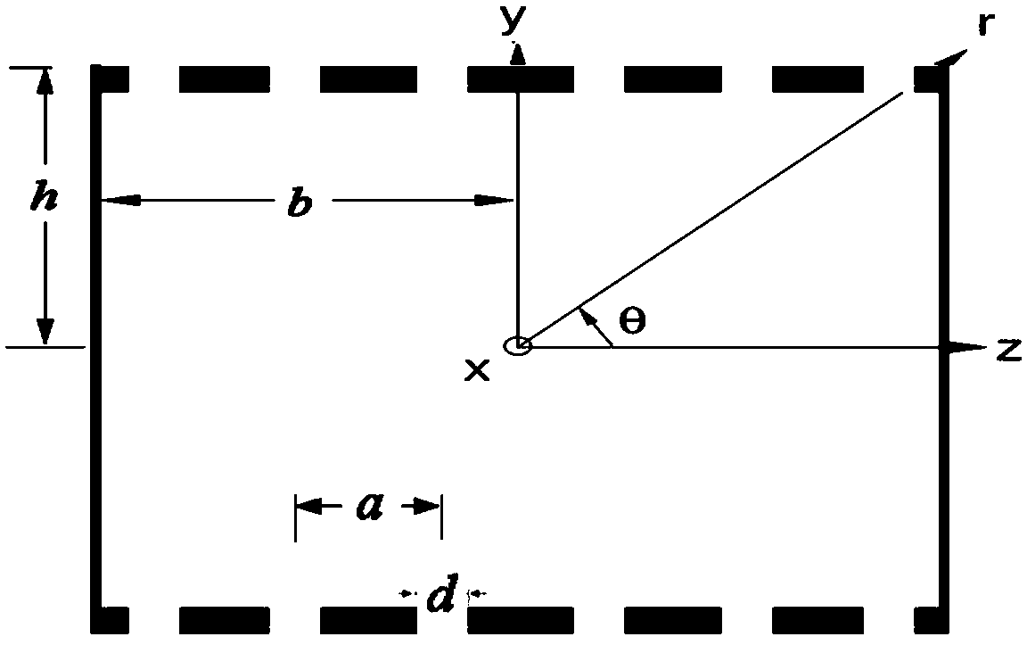
[0059] In this example, the method of the present invention is used to determine the reasonable grooving rate of a test section with a rectangular section, and the cross-sectional dimension of the test section is 2.4 meters (width, denoted as h) × 2.0 meters (height, denoted as b). The coordinate system is established with the center of the test model as the origin; the X-axis is along the axial direction of the test section; the Y-axis is perpendicular to the X-axis and points upward in the longitudinal symmetry plane of the model; the Z-axis is given according to the right-hand rule. figure 1 shown. The test section is in the form of upper and lower slots, left and right solid walls, and the number of slots is n=2b / a. A reasonable slotting ratio d / a is determined according to the method of the present invention to completely eliminate the blocking interference effect.


PUM


Abstract

The invention discloses a method for determining the slotting rate of a wind tunnel test section wallboard, and aims to eliminate a current situation that the existing design of the slotting rate of the transonic speed wind tunnel test section lacks a theoretical foundation. On the basis of the analysis of axial induced velocity distribution in a conventional model test, a method for determining areasonable slotting rate is put forward by taking blockage interference effect elimination as a foundation so as to improve the refining level of slot wall design and guide later-stage equipment operation and data analysis work. The slotting rate determined by the method disclosed by the invention is determined on the basis of complete model blockage interference effect elimination, and under thestate of the slotting rate, influences, including model lift force interference, streamline bending interference and the like, can not be ignored and still need to be evaluated and corrected. Since the model blockage interference directly influences wind tunnel running states (including test section entry Mach number, static pressure, Reynolds number and the like), the slotting rate should be preferentially based on blockage interface effect elimination. By use of the method, design risks and debugging cost can be effectively lowered, and the refining level of slot wall design can be improved.

Description

technical field [0001] The invention relates to the field of experimental aerodynamics, in particular to a method for determining the grooving rate of wall panels in a wind tunnel test section, which is a method for determining a reasonable grooving rate for wall panels in a transonic wind tunnel test section. Background technique [0002] In the transonic wind tunnel, in order to avoid blockage during operation and reduce the blockage effect in the subsonic speed range, the wall panels of the test section are all ventilated with holes or slots. In the high subsonic range, compared with the hole wall, the groove wall has the characteristics of less interference, low noise, convenient processing and adjustment, etc., making it gradually become the development trend of the transonic wind tunnel; the latest transonic equipment in Europe and America, such as ETW ( That is, European Transonic Windtunnel, European Transonic Wind Tunnel)), NTF (that is, National Transonic Facility)...

Claims


Application Information

Patent Timeline
Patent Type & Authority Patents(China)
IPC IPC(8): G01M9/02G01M9/04
CPCG01M9/02G01M9/04
Inventor 刘光远吴军强陈德华魏志刘大伟陶洋许新彭鑫熊贵天史晓军
Owner INST OF HIGH SPEED AERODYNAMICS OF CHINA AERODYNAMICS RES & DEV CENT
Why Eureka
Try Eureka