
LED solar simulator drive circuit control method and system

A technology of solar simulator and driving circuit, which is applied in the layout of electric lamp circuit, electric light source, lighting device, etc., can solve the problem that the constant current power supply simulator cannot be used directly.

Inactive Publication Date: 2016-01-27
李果华
View PDF5 Cites 0 Cited by
  • Summary
  • Abstract
  • Description
  • Claims
  • Application Information

AI Technical Summary

Problems solved by technology

The existing steady-current power supply in the market is restricted by the high requirements of the simulator and cannot be used directly

Method used


Image

  • LED solar simulator drive circuit control method and system
  • LED solar simulator drive circuit control method and system

Examples


Embodiment Construction

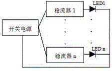
[0009] Realization of LED solar simulator control method: design single-sided (or double-sided) LED aluminum substrate, and realize single LED control circuit. There is no uniform regulation for circuit design, and it is enough to realize single LED control. In the LED solar simulator control, according to the illuminance of the LED solar simulator on the effective irradiation surface, properly adjust the LED drive current value of the corresponding area (by adjusting the resistance value of the precision adjustable resistor), reduce or strengthen the area Light intensity value to achieve uniform irradiation on the irradiated surface. The finer the LED control, the more precise the uniformity adjustment on the irradiated surface.

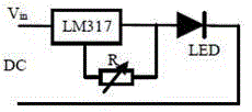
[0010] Realization of LED drive circuit. The LED steady current drive circuit realized in this design includes AC-DC switching power supply, LM317 three-terminal voltage regulator tube, precision adjustable resistor and radiator. The voltage value...


PUM


Abstract

The invention relates to a drive circuit control method and system of a solar simulator with high-power LED acting as light sources. Irradiation intensity of a local area can be conveniently controlled by adopting a single LED individual control method in view of the light source characteristic of LED array light sources of an LED solar simulator. Besides, a current-stabilizing driving method is adopted in LED driving in combination of the electrical characteristic of inconsistency of turn-on voltage between LED so that inconsistency of turn-on voltage can be overcome, and the stable and consistent light output effect of the LED can be achieved. A current-stabilizing drive circuit comprises an AC-DC switching power supply, an LM317 three-terminal voltage-stabilizing tube, a precision adjustable resistor and a heat radiator. The method is simple in circuit design, low in production cost and great in current stabilization effect.

Description

technical field [0001] The invention relates to a method for driving and controlling a light source of an LED solar simulator and an LED driving circuit. Background technique [0002] In the field of lighting technology, due to the obvious advantages of high luminous efficiency, energy saving, and long life, LEDs are widely used in various lighting tools. In recent years, it has become a reality to use high-power LEDs to make solar simulators, but solar simulators There are very high requirements on the uniformity of irradiation and the stability of irradiation. No one in China has conducted in-depth research on this. When using LEDs as the light source of the simulator, no one has designed the driving method and driving mode. The existing steady-current power supplies in the market are restricted by the high requirements of the simulator and cannot be used directly. [0003] Therefore, how to control the light source of the simulator and realize the high-required uniformit...

Claims


Application Information

Patent Timeline
IPC IPC(8): H05B37/02
Inventor 孙健刚李果华
Owner 李果华
Learn More