An ion wind cooling device

A technology of heat dissipation device and ion wind, applied in the direction of cooling/ventilation/heating transformation, can solve the problems of complex heat dissipation structure, large volume, vibration service life, etc., and achieve the effect of heat conduction

Active Publication Date: 2018-06-01
JIANGSU UNIV
View PDF8 Cites 2 Cited by
  • Summary
  • Abstract
  • Description
  • Claims
  • Application Information

AI Technical Summary

Problems solved by technology

They can all improve the heat dissipation effect of electronic devices to a certain extent, but there are some defects in these devices: the overall volume of the device is large, and the fans have problems such as noise, vibration and short service life.
However, this device has the following defects: ① The ion wind radiator only provides ion wind, and does not provide a heat conduction device. During the heat dissipation process, it is necessary to add heat conduction components such as fins at the heat source, and then install the ion wind heat sink, that is, the heat conduction part The heat dissipation part is installed independently, which makes the whole heat dissipation structure complex, occupies a large space and mass, reduces the heat dissipation efficiency, and increases the cost
②In the process of air ionization, the generation of ozone is inevitable, and the excessive ozone content will cause harm to the human body

Method used


Image

  • An ion wind cooling device
  • An ion wind cooling device
  • An ion wind cooling device

Examples


Embodiment 1

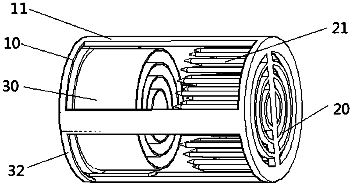
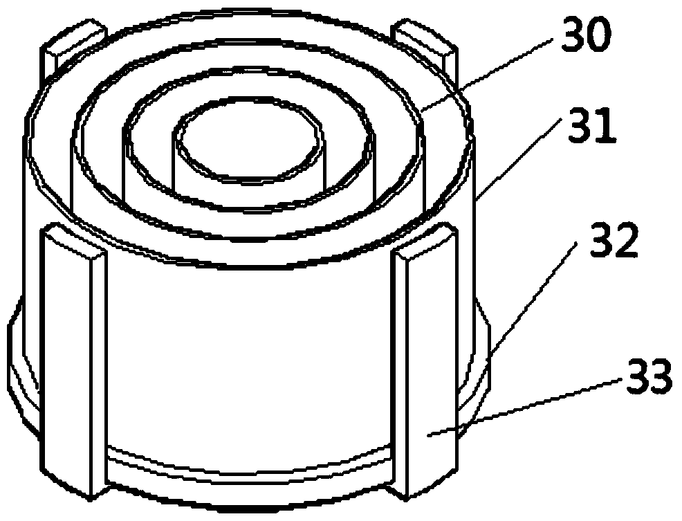
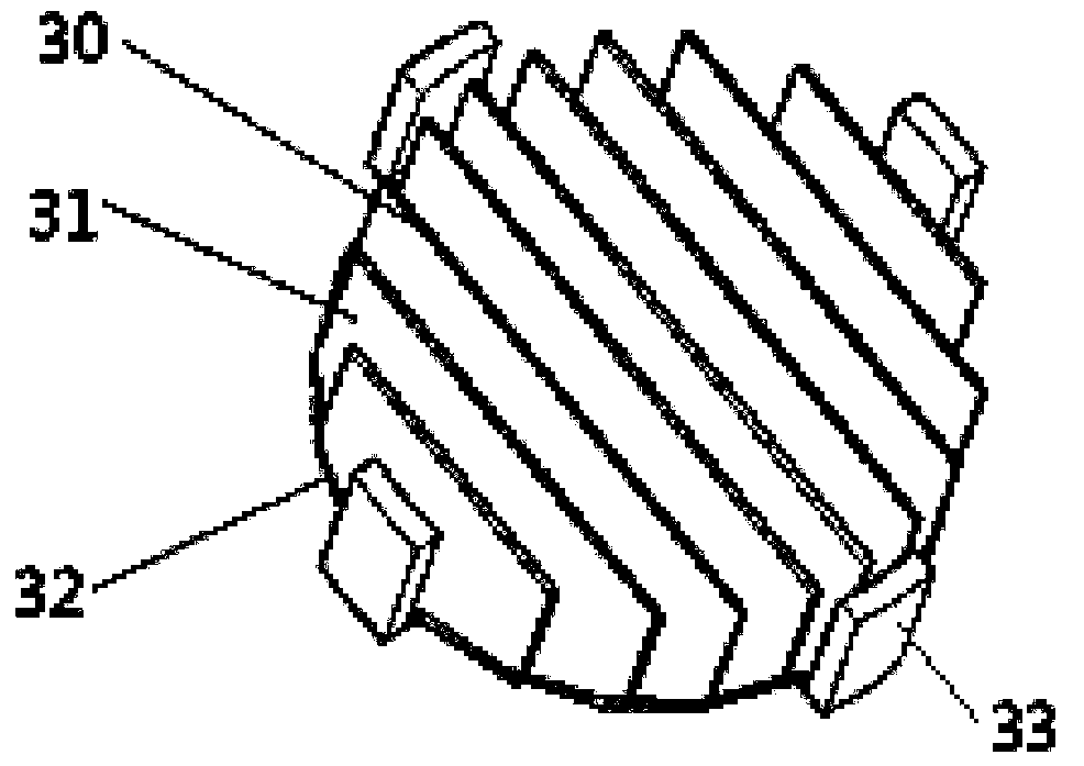
[0018] like figure 1 , figure 2 As shown, the ion wind cooling device of the present invention includes: a housing 10 and an ion wind generator. The ion wind generator is a corona discharge ion wind generator, including an emitter 20 and a receiver 30 . The housing 10 is composed of a bottom surface and several slide rails 11 vertically connected to the bottom surface. The emitter 20 of the ion wind generator is fixed on the free end of the slide rail 11 and is opposite to the bottom surface of the housing 10. Set to form the main frame of the ion wind generator. The emitter 20 and the housing 10 may be integrated, or two detachable independent parts. The emitter 20 is connected to the positive pole or the negative pole of the power supply, the receiving electrode of the ion wind generator is electrically connected to the ground wire, and several sliders 33 are arranged on the circumferential edge of the receiving pole 30, and the sliders 33 are mounted on on the slide ra...

Embodiment 2

[0021] like image 3 As shown, different from Embodiment 1, the receiving electrode 30 in this embodiment adopts a plate-like electrode, the array of the emitter 20 is strip-shaped, and the ozone filter coating 31 is coated on the receiving electrode 30 plate of the ion wind generating device. On the side of the shape electrode 30.


PUM


Abstract

The invention provides an ion wind cooling device, which is characterized in that it includes an insulating housing and an ion wind generator, the housing is composed of a bottom surface and several slide rails vertically connected to the bottom surface, the ion wind The emitter of the wind generator is fixed on the free end of the slide rail and is arranged opposite to the bottom surface of the housing, the emitter is connected to the positive or negative pole of the power supply, and several sliders are arranged on the circumferential edge of the receiving pole of the ion wind generator , the slider is installed on the slide rail, the receiving pole is electrically connected to the ground wire, an insulating heat-conducting substrate is fixed on the back of the receiving pole, the heat-conducting substrate is fixed on the bottom surface of the housing, and the surface of the receiving pole is also Coated with an ozone filter coating. The structure design of the present invention enables the ion wind generator to have triple functions of generating ion wind, effectively conducting heat, and removing ozone generated during the ionization process. The distance between the receiving pole and the emitter of the ion wind generator can also be adjusted to adjust the wind speed of the ion wind.

Description

technical field [0001] The invention relates to an ion wind cooling device. Background technique [0002] As the majority of users have higher and higher requirements for electronic products in terms of small size, light weight, safety and environmental protection, the application of highly integrated, compact structure, and high-performance chips has become the development trend of electronic products. However, the heat flux density of electronic devices is high, and the heat cannot be discharged in a small space in time, which will inevitably affect the service life and reduce work efficiency. [0003] Traditional cooling devices can be divided into three categories: ① natural convection cooling devices based on fins and heat pipes; ② forced convection cooling devices based on fans; ③ cooling devices that combine the two. All of them can improve the heat dissipation effect of electronic devices to a certain extent, but these devices all have some defects: the overall volu...

Claims


Application Information

Patent Timeline
Patent Type & Authority Patents(China)
IPC IPC(8): H05K7/20
Inventor 蔡忆昔李慧霞王静包伟伟
Owner JIANGSU UNIV
Why Eureka
Try Eureka