Brake device for vehicle

一种制动装置、车辆的技术,应用在制动作用启动装置、制动器、车辆部件等方向,能够解决制动操作量变化、无法应对等问题,达到减速度的变化平稳、增大增长效果、抑制减速度的变化的效果

Active Publication Date: 2016-01-27
HONDA MOTOR CO LTD
View PDF6 Cites 3 Cited by
  • Summary
  • Abstract
  • Description
  • Claims
  • Application Information

AI Technical Summary

Problems solved by technology

[0008] However, as an input factor of the brake control, there is not only the vehicle speed but also the change of the brake operation amount (brake pedal stroke amount) operated by the driver, so there is a problem that the brake operation amount changes during the brake operation. Unable to cope with changing circumstances

Method used


Image

  • Brake device for vehicle
  • Brake device for vehicle
  • Brake device for vehicle

Examples


Embodiment Construction

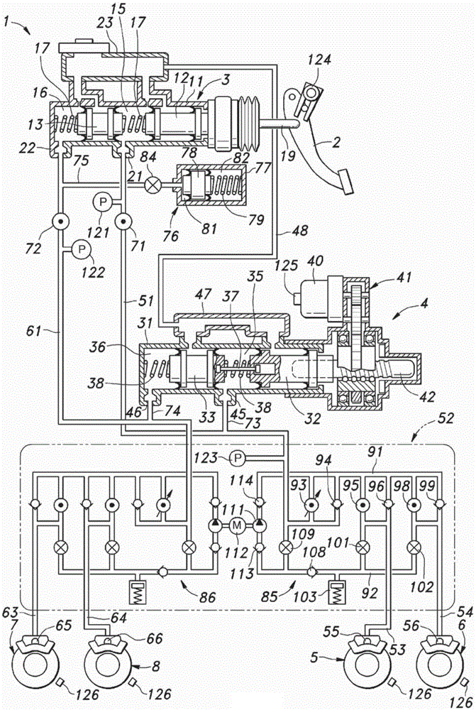
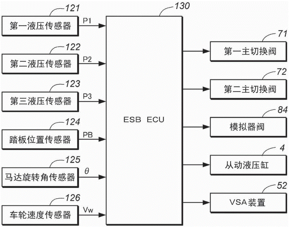
[0030] Hereinafter, embodiments of the present invention will be described with reference to the drawings. figure 1 is a diagram showing a hydraulic circuit of the vehicle brake device 1, figure 2 It is a block diagram of the control system of the vehicle brake system. Such as figure 1 and figure 2 As shown, the vehicle braking device 1 of the embodiment has: a brake pedal 2 as a brake operating member, which is rotatably supported on the vehicle body; and the disc brakes 5, 6, 7, 8, which are driven by the hydraulic pressure of the master hydraulic cylinder 3 or the slave hydraulic cylinder 4.

[0031] The main hydraulic cylinder 3 is a tandem hydraulic cylinder, and has a cylindrical main-side housing 11 and a main-side first piston 12 and a main-side second piston 13 housed in the main-side housing 11 so as to be displaceable. . The first master-side piston 12 is disposed on the rear side in the main-side housing 11 along the axial direction, and the second master-si...


PUM


Abstract

In order to perform favorable buildup control even in cases where not only the vehicle speed but also the brake operation amount changes during brake operation, a target control value of a brake fluid pressure to be generated in accordance with the brake operation amount is set by employing: a first coefficient that is set on the basis of the vehicle speed within an initial period of the driver's brake operation; and a second coefficient that is set in accordance with changes in the brake operation amount and the vehicle speed during braking. Thus, in the initial brake-operation period, the amount of increase for buildup can be reduced, and thereby, it is possible to respond to the vehicle speed and to moderate the occurrence of deceleration within the initial braking period due to the brake operation amount. During breaking, a favorable buildup effect can be achieved by increasing deceleration in accordance with reduction in vehicle speed.

Description

technical field [0001] The invention relates to a braking device for a vehicle, in particular to a braking device for a vehicle which generates braking force through an electric actuator. Background technique [0002] Conventionally, there is a so-called brake-by-wire vehicle braking device in which brake pressure is generated by a hydraulic cylinder using an electric actuator that uses an electric motor as a drive source. On the other hand, in the case of braking with a constant depression amount due to mechanical reasons of the brake device, there is a possibility that the braking force is insufficient in the second half of the braking, and the deceleration cannot be performed according to the deceleration intended by the driver. Phenomenon. Therefore, in order to obtain a desired deceleration, the driver may need to increase the depression of the brake pedal. In this case, the brake operation becomes complicated. [0003] When the electric actuator is driven by brake-by...

Claims


Application Information

Patent Timeline
Patent Type & Authority Applications(China)
IPC IPC(8): B60T8/17B60T8/00B60T8/58
CPCB60T8/4081B60T7/042B60T13/146B60T13/686B60T13/745B60T2201/03B60T2220/04B60T13/662
Inventor 石野圭亮冈田周一赤峰宏平波多野邦道
Owner HONDA MOTOR CO LTD
Why Eureka
Try Eureka