
Vehicle controlling device and method

一种控制装置、控制方法的技术,应用在传动装置、传动装置控制、带有齿的元件等方向,达到拖拽损失抑制、提高耐久性的效果

Inactive Publication Date: 2016-01-27
TOYOTA JIDOSHA KK
View PDF7 Cites 5 Cited by
  • Summary
  • Abstract
  • Description
  • Claims
  • Application Information

AI Technical Summary

Problems solved by technology

Therefore, in a vehicle including a transmission device in which the above-mentioned stepped transmission portion and the continuously variable transmission portion are arranged in parallel, when the control to stop the internal combustion engine is executed, the clutch for switching the above-mentioned transmission path is engaged or There is room for improvement in terms of the control that is released and set to the neutral state

Method used


Image

  • Vehicle controlling device and method
  • Vehicle controlling device and method
  • Vehicle controlling device and method

Examples


Embodiment Construction

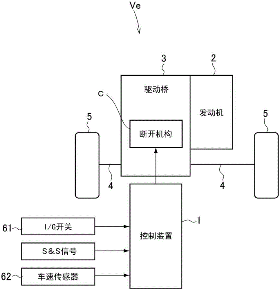
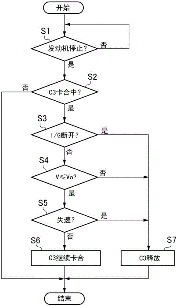
[0024] Hereinafter, the present invention will be described based on specific examples. The vehicle targeted by the present invention is configured to execute S&S control and stop an internal combustion engine as a power source when a predetermined condition is satisfied while the vehicle is stopped or running. That is, the S&S control is executed according to the parking state or the running state while the ignition switch, which is the main switch of the vehicle, is in the ON state. Therefore, the vehicle control device according to the present invention is configured to switch the disconnector for connecting or disconnecting the torque transmission path between the internal combustion engine and the drive wheels according to the running state or the parking state of the vehicle when the internal combustion engine is stopped. Control the work of the open agency.

[0025] Furthermore, the vehicle as the object of the present invention is provided with a speed change device i...


PUM


Abstract

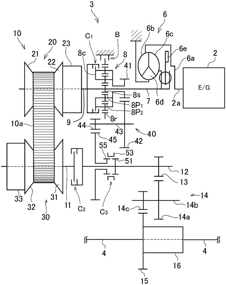
Provided are a vehicle controlling device and method wherein the operation of a clutch mechanism is controlled according to the traveling state or the stopped state of a vehicle at the time an engine is stopped for the vehicle that comprises a transmission path that includes a stepped transmission unit, a transmission path that includes a continuously variable transmission unit and is provided parallel to the stepped transmission unit, and the clutch mechanism for switching the transmission path. The vehicle controlling device comprising, between an input shaft and an output shaft, the continuously variable transmission unit that continuously changes the gear ratio, the stepped transmission unit that is provided in parallel with the continuously variable transmission unit and that can set a gear ratio that cannot be set with the continuously variable transmission unit, and a clutch mechanism that is provided in the torque transmission path between the stepped transmission unit and a drive wheel, is configured so that the clutch mechanism is released when the vehicle speed is at a prescribed value or higher and the engine is stopped.

Description

technical field [0001] The present invention relates to a control device and method for a vehicle. The control device includes a clutch for connecting or disconnecting a torque transmission path between a transmission device and drive wheels. Background technique [0002] It is widely known that the torque transmitted from the drive wheels of the vehicle is not transmitted to the transmission. For example, Japanese Patent Application Laid-Open No. 2002-89706 describes a vehicle that includes, on the torque transmission path between the toroidal continuously variable transmission and the drive wheels, an auxiliary transmission including a plurality of transmission paths with different gear ratios. ; A clutch used to connect or disconnect any one of the transmission paths in the auxiliary transmission part and the toroidal continuously variable transmission. [0003] In addition, the control device described in Japanese Unexamined Patent Publication No. 2002-89706 is configur...

Claims


Application Information

Patent Timeline
Patent Type & Authority Applications(China)
IPC IPC(8): F16H61/02F16D48/02F16H37/02
CPCF16H37/022F16D48/06F16D48/062F16D2500/1088F16D2500/30401F16D2500/306F16D2500/3069F16D2500/3111F16D2500/50858F16D2500/7041F16H2037/026F16H37/0846F16H61/70
Inventor 谷中悟史中田博文吉田伦生近藤宏纪松尾贤治石泉和也井上大辅铃村京平
Owner TOYOTA JIDOSHA KK
Learn More