
A modular waste gas treatment device

An exhaust gas treatment device and modular technology, which is applied in combination devices, chemical instruments and methods, dispersed particle filtration, etc., can solve the problems of single use, unsatisfactory purification effect, inconvenient replacement, etc. Equipment utilization, good effect of purification treatment

Active Publication Date: 2017-07-28
SUZHOU RHYMEBLUE ENVIRONMENTAL TECH CO
View PDF9 Cites 0 Cited by
  • Summary
  • Abstract
  • Description
  • Claims
  • Application Information

AI Technical Summary

Problems solved by technology

[0003] Traditional exhaust gas treatment devices mainly use activated carbon for adsorption. Activated carbon purification is a physical process. The exhaust gas that only passes through activated carbon also contains some impurities and dust. The purification effect is not ideal, and in order to reduce the diffusion of harmful gases, it is necessary to use chemical methods for purification At present, there are chemical absorption method, catalytic combustion method, plasma purification method, etc., these methods are relatively single, and cannot fully achieve the purification effect
[0004] Moreover, traditional waste gas treatment devices are generally specially produced treatment equipment for the specific waste gas objects to be treated, and the required substances are added to the equipment in advance. In order to ensure airtightness, it is inconvenient to replace, so its scope of application is small. It cannot be used with multiple waste gases or can still be used after the purification object is changed. There are deficiencies in one-time investment, high energy consumption for equipment operation, and great limitations in flexibility, which directly lead to incompatible performance of the equipment.

Method used


Image

  • A modular waste gas treatment device
  • A modular waste gas treatment device

Examples


Embodiment Construction

[0022] Below in conjunction with accompanying drawing of description, the present invention will be further described.

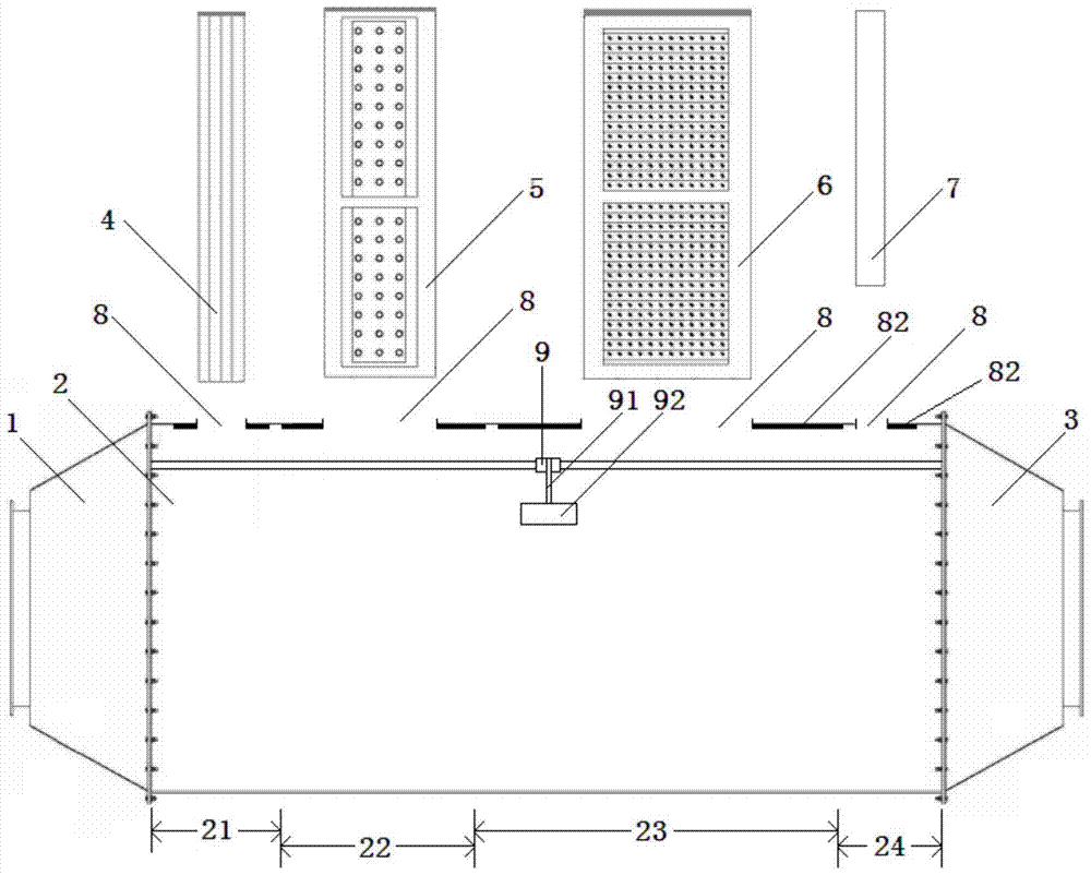
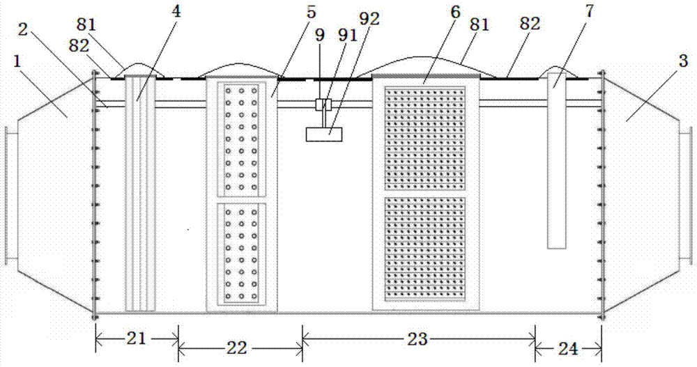
[0023] Such as figure 1 and figure 2 As shown, a modular exhaust gas treatment device includes an inlet pipe 1, a processing pipe 2, and an outlet pipe 3 connected in sequence; The coarse filter area 21 of group 4 is provided with the fine filter area 22 of at least one fine filter module 5, is provided with the special treatment area 23 of at least one special treatment module 6, and is provided with at least one detection module 7 before the air outlet Detection zone 24.

[0024] The top pipe wall of the processing tube 2 where the coarse filter area 21, the fine filter area 22, the special treatment area 23 and the pre-outlet detection area 24 are all provided with at least one assembly window 8, the coarse filter module 4, the fine filter module The filter module 5, the special treatment module 6 and the detection module 7 are all installed in the pr...


PUM


Abstract

The invention discloses a modular exhaust gas treatment device, which comprises an inlet pipe, a treatment pipe and an air outlet pipe connected in sequence; the treatment pipe is sequentially divided into a coarse filtration area provided with at least one coarse filtration module and at least one fine filtration module The fine filter area of ​​the group is equipped with a special treatment area with at least one special treatment module, and a pre-exit detection area with at least one detection module; the top pipe wall of the treatment tube where each area is located is provided with at least one assembly window, Coarse filter module, fine filter module, special treatment module and detection module are all installed in the processing tube of each area by inserting into the assembly window, and cover the assembly window; the side wall of the processing tube is equipped with A sliding rail, on which a sliding frame is installed; the sliding frame includes a bracket connected to the sliding rail, and an additional processing module connected to the bracket with a variable processing sequence. The equipment has flexible compatibility and modular combination functions, and can be used for replacement of various exhaust gases through equipment changes.

Description

technical field [0001] The invention relates to a waste gas treatment device, in particular to a modular waste gas treatment device, which belongs to the technical field of environmental protection equipment. Background technique [0002] Waste gas treatment mainly refers to the work of treating industrial waste gas such as dust particles, flue gas smoke, odorous gas, and toxic and harmful gases generated in industrial places. Common waste gas treatment includes factory smoke and dust waste gas treatment, workshop dust waste gas treatment, organic waste gas treatment, waste gas odor purification, acid and alkali waste gas treatment, chemical waste gas treatment, etc. Exhaust gas treatment equipment is widely used in chemical factories, electronics factories, paint factories, automobile factories, paint factories, petrochemical industries, furniture factories, food factories, rubber factories, plastic factories and other industries that produce odor, odor, toxic and harmful g...

Claims


Application Information

Patent Timeline
Patent Type & Authority Patents(China)
IPC IPC(8): B01D46/00B01D50/00B01D53/00B01D53/86B01D53/76B01D53/32
Inventor 胡云猛武家伟
Owner SUZHOU RHYMEBLUE ENVIRONMENTAL TECH CO
Learn More