
Molding technology for crankshaft forged piece flanges capable of being accurately grabbed by robot

A robot and flash technology, which is applied in the field of crankshaft forging and forming, can solve the problem that the robot cannot accurately grasp the flash, and achieve the effects of high accurate grasping rate, improved production efficiency, and stable flash forming

Active Publication Date: 2016-02-03
桂林福达重工锻造有限公司
View PDF5 Cites 1 Cited by
  • Summary
  • Abstract
  • Description
  • Claims
  • Application Information

AI Technical Summary

Problems solved by technology

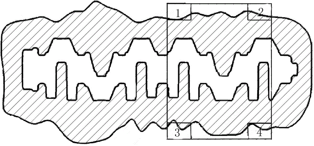
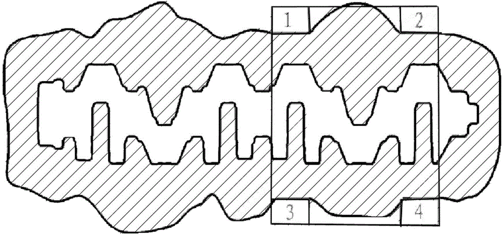
[0003] The purpose of the present invention is to solve the problem that the robot cannot accurately grasp the flash by making the flash shaping table on the pre-forging lower die and the final forging lower die of the crankshaft, and by setting the flash of the forging

Method used


Image

  • Molding technology for crankshaft forged piece flanges capable of being accurately grabbed by robot
  • Molding technology for crankshaft forged piece flanges capable of being accurately grabbed by robot

Examples


Embodiment

[0016] A flash forming process for crankshaft forgings that can be adapted to accurate grasping by robots, comprising the following steps:

[0017] 1) Design the flash positioning platform: use CAE technology, use FORGE software to simulate and analyze the shape of the flash, so as to determine the size of the flash, and then design the flash positioning platform; among them, in order to prevent the flash formed by pre-forging and final forging There is interference in the flash positioning table, and the horizontal and radial dimensions of the pre-forging positioning table are increased by 5mm compared with the final forging positioning table;

[0018] 2) Processing flash positioning table: according to the designed flash positioning table style, the pre-forging lower die and the final forging lower die's flash grabbing position are surfacing welded, and then the positioning table is processed by the machining center, and at the same time Make a positioning platform avoidance...


PUM


Abstract

The invention discloses a molding technology for crankshaft forged piece flanges capable of being accurately grabbed by a robot. The molding technology comprises the following steps: utilizing a CAE technology, stimulating and analyzing the shapes of pre-forged flanges and finish-forged flanges by using an FORGE software, determining the sizes of the flanges according to the shapes, designing the position of a flange positioning table, and finally molding the flanges. The technology has the advantages that the molding of the crankshaft forged piece flanges is stable, the accurate grabbing rate of the robot is high, fully-automatic forging is guaranteed, and the production profitability is substantially improved.

Description

technical field [0001] The invention relates to crankshaft forging molding, in particular to a forging flash shaping process that can be accurately grasped by a robot during the crankshaft forging process. Background technique [0002] In the process of forging the crankshaft blank, when the forging is transferred from the die forging to the trimming process, due to the irregular shape of the flash of the forging, the robot grabs the material inaccurately, and the position of the robot grabbing the material often collides with the flash. If this situation occurs during production, the production line must be stopped to adjust the robot's grabbing position. At the same time, it will cause problems such as intermediate frequency furnace throwing, and other processes are waiting for work, resulting in unnecessary waste in many aspects. Contents of the invention [0003] The purpose of the present invention is to solve the problem that the robot cannot accurately grasp the fla...

Claims


Application Information

Patent Timeline
Patent Type & Authority Applications(China)
IPC IPC(8): B21K1/08
Inventor 李国旗谢贵超王春明
Owner 桂林福达重工锻造有限公司
Learn More