Roll angle self-adaptive adjusting clamp

A technology of self-adaptive adjustment and roll angle, applied in the field of machinery, can solve the problems of different depths of the file pattern on the left and right, the reduction of the forming quality of the file, and the scrapping, etc., to achieve the effect of improving the processing efficiency and the adjustment quality, and the adjustment is convenient.

Active Publication Date: 2016-02-03
中国兵器装备集团自动化研究所有限公司
View PDF7 Cites 4 Cited by
  • Summary
  • Abstract
  • Description
  • Claims
  • Application Information

AI Technical Summary

Problems solved by technology

During the chopping process, it is necessary to keep the plane of the file parallel to the edge of the chopping tool, so as to avoid the left and right depths of the same file being processed, which will cause the quality of the file to decline or even be scrapped.

Method used


Image

  • Roll angle self-adaptive adjusting clamp
  • Roll angle self-adaptive adjusting clamp
  • Roll angle self-adaptive adjusting clamp

Examples


Embodiment 1

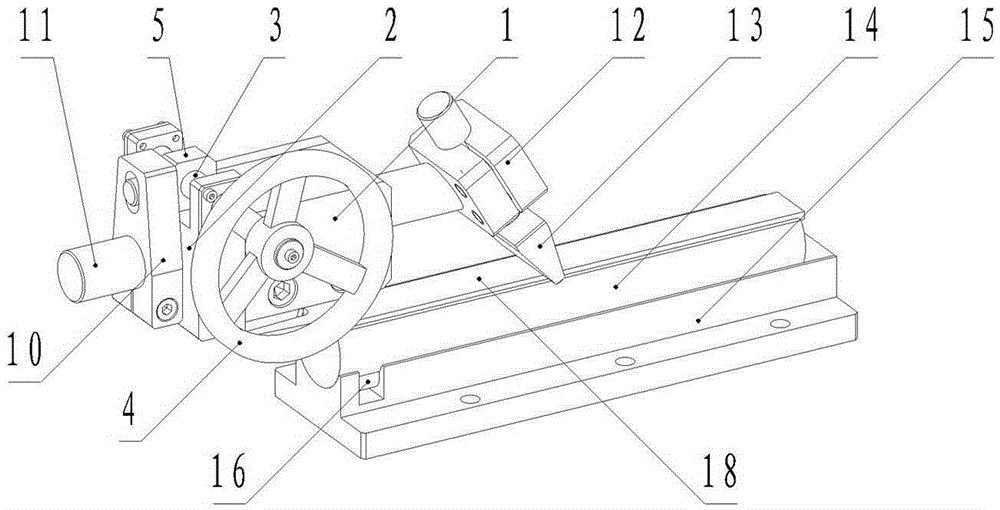
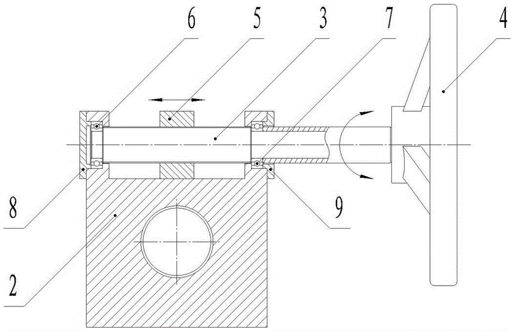
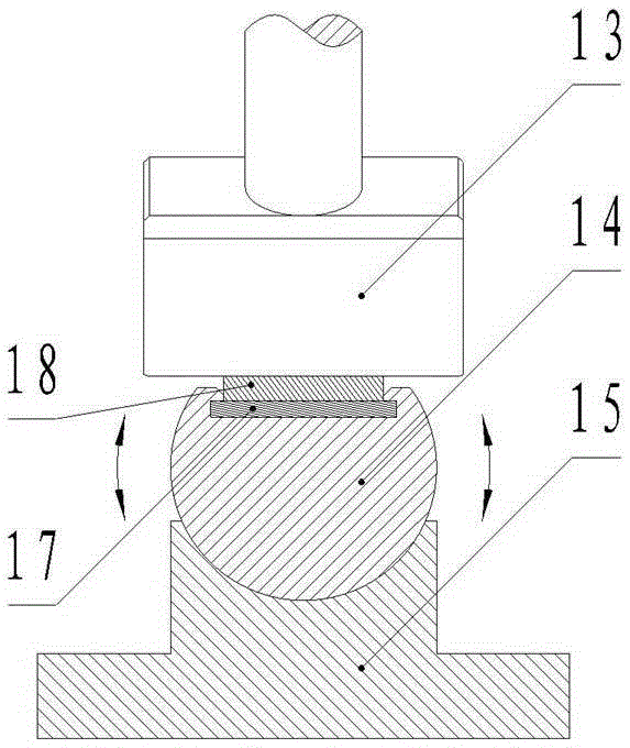
[0015] exist Figure 1 ~ Figure 3 Among them, the clamp for self-adaptive adjustment of the roll angle of the present invention includes a roll clamping block 1, an adjustment screw seat 2, an adjustment screw 3, a hand wheel 4, an adjustment nut 5, a screw bearing one 6, a screw bearing two 7, and a bearing gland 18. Bearing gland 29. Roll swing arm 10, roll shaft 11, presser foot clamp block 12, inverted T-shaped presser foot 13, clamp platform 14, clamp base 15, clamp key 16, backing plate 17, File 18. The roll clamping block 1 is fixedly connected to the machine bed, and the middle part is provided with a horizontal clamping hole, which is used to place the roll shaft 11 horizontally, and the roll shaft 11 with the adjusted roll angle can be clamped tight; the adjusting screw seat 2 is firmly connected to the roll clamping block 1, and there is a bearing mounting hole on both sides and a set of threaded holes for mounting the bearing cover correspondingly, for installing ...

Embodiment 2

[0018] The basic structure of this embodiment is the same as that of Embodiment 1, except that the manual rotation of the hand wheel to drive the rotation of the adjustment screw 3 is changed to the rotation of the motor to drive the rotation of the adjustment screw 3 .


PUM


Abstract

The invention provides a roll angle self-adaptive adjusting clamp. A roll clamping block is fixedly connected with a machine tool body; an adjusting screw seat is fixed to the roll clamping block; an adjusting screw is installed in the middle of the adjusting screw seat; a hand wheel is connected with one end of the adjusting screw; an adjusting nut and the adjusting screw are connected in a thread matched mode; one end of a roll swing arm is connected with a roll shaft; the other end of the roll swing arm is connected with a small shaft of the adjusting nut; the roll shaft horizontally penetrates through a clamping hole of the roll clamping block; one end of the roll shaft is connected with the roll swing arm; the other end of the roll shaft is connected with a presser foot clamping block; the lower portion of an inverted T-shaped presser foot tightly presses the upper plane of a file; the length direction of the long side of the lower portion of the inverted T-shaped presser foot is parallel to the axis of the adjusting screw; the file is arranged on a clamp platform, and a base plate is cushioned between the file and the clamp platform; a clamp base is fixedly connected to a machine tool workbench; the clamp platform is arranged above the clamp base.

Description

technical field [0001] The invention relates to a side tilt angle self-adaptive adjustment fixture, which belongs to the field of machinery. The invention can be used for micro-adjustment of the side inclination angle of the file fixture during the process of chopping the teeth of the file, so as to realize the parallelism between the plane of the file and the blade of the chopping tool. Rotating the handwheel in the present invention can easily change the tilting posture of the presser foot of the platform, thereby changing the tilting angle of the fixture platform. Background technique [0002] The tooth pattern of the file is realized by the chopping process. The principle is to chop the tooth-shaped file pattern on the file blank through the up and down cutting movement of the tooth chopping tool and the horizontal feed movement of the file fixture, so as to complete the tooth pattern of the file. Production. During the chopping process, it is necessary to keep the pla...

Claims


Application Information

Patent Timeline
Patent Type & Authority Applications(China)
IPC IPC(8): B23Q3/04B23D69/00
CPCB23D69/00B23Q3/04
Inventor 刘玲周晓华王敏雷珂欧阳长青
Owner 中国兵器装备集团自动化研究所有限公司
Why Eureka
Try Eureka