Controllable elevated working platform

A technology for lifting and lowering workbenches and tabletops, which is applied in the direction of workbenches and manufacturing tools, can solve the problems that the workbench has no folding function, cannot provide a workbench, is unfavorable for carrying and handling, etc., so as to avoid wasting labor, improve work quality, small size effect

Inactive Publication Date: 2016-02-03
STATE GRID CORP OF CHINA +1
View PDF0 Cites 2 Cited by
  • Summary
  • Abstract
  • Description
  • Claims
  • Application Information

AI Technical Summary

Problems solved by technology

[0002] In the process of electric power maintenance work, many tasks need to be completed on the workbench, such as placing precision instruments, handling cable ends, processing busbars, simple transformation of machine parts, etc., especially emergency repair work of electric power, which is an emergency and needs to be rushed to the accident as soon as possible Troubleshooting on-site and eliminating defects in a timely manner requires the staff to carry all the tools in a short period of time and quickly set off on the construction vehicle. However, the old-fashioned workbenches do not have the folding function and are large in size, which is not conducive to Carrying, handling, and there are many types of electric maintenance work vehicles, and some maintenance work vehicles (such as off-road vehicles, vans) cannot meet the workbench handling conditions, and there is another situation where maintenance or construction work sites are crowded and narrow , nor can it provide the conditions for the workbench to be moved in and out, so a new workbench that is flexible in operation, foldable, small in size, portable by one person, strong in material, and corrosion-resistant is required to meet the needs of power maintenance and construction work

Method used


Image

  • Controllable elevated working platform
  • Controllable elevated working platform
  • Controllable elevated working platform

Examples


Embodiment Construction

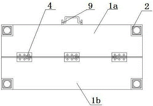
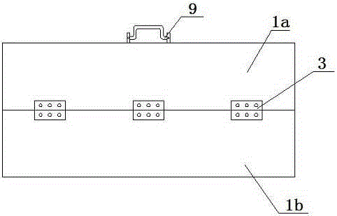
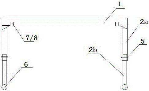
[0018] Such as figure 1 , figure 2 , image 3 , Figure 4 and Figure 5 As shown, a controllable lifting workbench includes a platform 1 and legs 2, the legs 2 are foldably installed on the bottom surface of the platform 1 through a hinge, and the platform includes a hinge 3 The hinged first deck 1a and the second deck 1b are provided with a locking mechanism 4 at the folds of the first deck 1a and the second deck 1b. repeat; such as Figure 4 As shown, the legs include a first leg 2a and a second leg 2b, the second leg 2b is telescopically inserted into the first leg 2a from bottom to top, and the first leg 2a and the second leg 2b is provided with matching slots, and positioning screws 5 are arranged in the slots, and the positioning screws 5 pass through the slots 2d on the first leg 2a and the second leg 2b successively and are fastened by nuts. To adjust the height of the legs, a scale 2c is provided on the outer peripheral wall of the slot of the first leg 2a; in ...


PUM


Abstract

The invention relates to a controllable elevated working platform which comprises a platen and supporting legs. The supporting legs are mounted on the bottom surface of the platen through hinges in a foldable mode. The platen comprises a first platen body and a second platen body which are hinged through hinges. Locking mechanisms are arranged at the folding position of the first platen body and the second platen body. Each supporting leg comprises a first supporting leg body and a second supporting leg body. Each second supporting leg body is inserted into the corresponding first supporting leg body from bottom to top in a telescopic mode. Each first supporting leg body and the corresponding second supporting leg body are provided with matched slotted holes. Positioning screws are arranged in the slotted holes. The positioning screws sequentially penetrate through the slotted holes in the first supporting leg bodies and the second supporting leg bodies and are fastened through nuts. The working platform is made of firm, light and corrosion-resistant materials and is foldable and convenient to carry, the space occupancy can be reduced greatly, the working efficiency is improved, unnecessary labor force waste is avoided, and overhaul quality is promoted.

Description

technical field [0001] The invention is aimed at the lack of workbenches in the electric power maintenance operation site, which causes inconvenience in construction. The use of the invention can avoid wasting labor force, increase work efficiency, and improve work quality. Background technique [0002] In the process of electric power maintenance work, many tasks need to be completed on the workbench, such as placing precision instruments, handling cable ends, processing busbars, simple transformation of machine parts, etc., especially emergency repair work of electric power, which is an emergency and needs to be rushed to the accident as soon as possible Troubleshooting on-site and eliminating defects in a timely manner requires the staff to carry all the tools in a short period of time and quickly set off on the construction vehicle. However, the old-fashioned workbenches do not have the folding function and are large in size, which is not conducive to Carrying, handling,...

Claims


Application Information

Patent Timeline
Patent Type & Authority Applications(China)
IPC IPC(8): B25H1/16B25H1/04
CPCB25H1/16B25H1/04
Inventor 宋明许德欣隋忠发邓树宏辛言明高海涛赵尧李世旭于善尧于铮李玲君
Owner STATE GRID CORP OF CHINA
Why Eureka
Try Eureka