Conveying belt type automatic feeding device

A technology of automatic feeding and conveyor belt, applied in the direction of conveyor objects, transportation and packaging, etc., can solve the problem that the time rhythm of conveying workpieces cannot be controlled, the conveyor belt cannot meet the transportation requirements, and the placement position and direction cannot be controlled. Wide, simple structure, low cost effect

Active Publication Date: 2016-02-03
WUXI MICRO RES PRECISION PRESS PARTS
View PDF5 Cites 6 Cited by
  • Summary
  • Abstract
  • Description
  • Claims
  • Application Information

AI Technical Summary

Problems solved by technology

The conveyor belt is driven by the motor, and the placement position and direction of the workpiece cannot be controlled, nor can the timing of the workpiece be controlled.
In actual production, the feeding position and direction of some workpieces have special requirements, and the traditional conveyor belt cannot meet the requirements for the feeding position and direction of the workpiece.

Method used


Image

  • Conveying belt type automatic feeding device
  • Conveying belt type automatic feeding device

Examples


Embodiment Construction

[0013] Below the present invention will be further described in conjunction with the embodiment in the accompanying drawing:

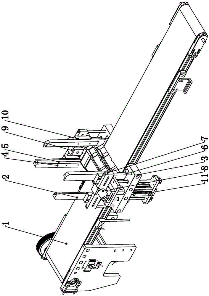
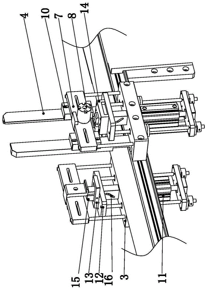
[0014] Such as Figure 1~2 As shown, the present invention mainly comprises conveyor belt 1 and the automatic feeding device 2 that is connected on both sides of conveyor belt 1 by bolts, and automatic feeding device 2 comprises discharging mechanism, locking mechanism, feeding mechanism and fixed plate 3, and fixed plate 3 From top to bottom, there are discharging mechanism, locking mechanism and feeding mechanism in sequence.

[0015] The discharge mechanism includes four discharge limit rods 4 fixed on the transmission belt 1. The four discharge limit rods 4 are symmetrically distributed in pairs on both sides of the conveyor belt 1. The inner side of each discharge limit rod 4 is provided with a discharge Feed trough 5. Four discharge limit rods 4 constitute the vertical channel for workpiece loading, and the workpiece can be accurately loaded th...


PUM


Abstract

The invention relates to a conveying belt, in particular to a conveying belt type automatic feeding device, and belongs to the technical field of conveying equipment. The conveying belt type automatic feeding device comprises a conveying belt and automatic feeding units connected to the two sides of the conveying belt through bolts. Each automatic feeding unit comprises a discharging mechanism, a locking mechanism, a feeding mechanism and a fixing plate, wherein the discharging mechanism, the locking mechanism and the feeding mechanism are sequentially arranged on the fixing plate from top to bottom. The conveying belt type automatic feeding device is simple, compact and reasonable in structure and works stably and reliably. The positions and directions of workpieces placed on the conveying belt can be accurately controlled. Meanwhile, conveying takt time is controlled accurately. Maintenance is convenient, and the cost is low. The requirement for conveying the workpieces of different dimensions can be met, and the application range is broad.

Description

technical field [0001] The invention relates to a conveyor belt, in particular to an automatic feeding device for a conveyor belt, which belongs to the technical field of conveyor equipment. Background technique [0002] In the prior art, the workpieces on the production line are conveyed through the conveyor belt. The conveyor belt is driven by a motor, and the placement position and direction of the workpiece cannot be controlled, nor can the time beat of conveying the workpiece. However, in actual production, some workpieces have special requirements for the feeding position and direction, and the traditional conveyor belt cannot meet the requirements for the feeding position and direction of the workpiece. Contents of the invention [0003] The purpose of the present invention is to overcome the above disadvantages, thereby providing an automatic feeding device for conveyor belts, which can accurately control the position and direction of workpieces placed on the conv...

Claims


Application Information

Patent Timeline
Patent Type & Authority Applications(China)
IPC IPC(8): B65G47/04
Inventor 谈渊智谈祖清孙伟亮
Owner WUXI MICRO RES PRECISION PRESS PARTS
Why Eureka
Try Eureka