
Rotation-controlled high altitude cable robot climbing mechanism

A robot and cable technology, applied in the field of cable-stayed bridge cable detection robots, can solve the problems of surface protection layer damage, wire breakage and lifting, troublesome adjustment, etc., achieving strong pipe diameter adaptability, complete and comprehensive detection, and control. Easy to install effect

Active Publication Date: 2016-02-03
NANJING UNIV OF POSTS & TELECOMM
View PDF5 Cites 7 Cited by
  • Summary
  • Abstract
  • Description
  • Claims
  • Application Information

AI Technical Summary

Problems solved by technology

[0002] The robot in the prior art is uncontrollable in the degree of freedom of rotation, so it cannot complete the inspection of the entire outer cylindrical surface
[0003] In addition, most of the existing robots have complex structures, heavy weight, weak climbing ability, and weak ability to overcome obstacles. It is troublesome to adjust when adapting to different pipe diameters. For example, when the pipe diameter is different, the posture of the mechanism is different, and the elongation length of the spring is different. , in order to ensure a constant pressing force of the roller, the spring needs to be replaced frequently, and the adjustment is quite troublesome
[0004] In addition, due to the long-term use of the cable and the harsh environment, the surface protection layer is often damaged, causing the internal steel wire to break and warp
Climbing robots can easily get caught when passing through these obstacles, and are forced to stay on the high-altitude cables and cannot successfully return to the ground
And the climbing robot stays on the high-altitude cable, which is very dangerous in itself

Method used


Image

  • Rotation-controlled high altitude cable robot climbing mechanism
  • Rotation-controlled high altitude cable robot climbing mechanism
  • Rotation-controlled high altitude cable robot climbing mechanism

Examples


Embodiment 1

[0074] Embodiment 1: Each probe includes a section of arc probe and a needle valve.

Embodiment 2

[0075] Embodiment 2: Each probe includes a section of arc-shaped probe and two needle valves arranged parallel to each other.

[0076] As an alternative, the number of needle valves may also be 3 or more, all of which are within the protection scope of the present application.

[0077] One end of each needle valve is fixedly connected to the arc probe, preferably the top of the needle valve is fixedly connected to the middle of the arc probe.

[0078] The other end of the needle valve is floatingly connected with the switch body, and the needle valve can trigger the conduction and disconnection of the switching signal in the switch body.

[0079] The above-mentioned arc probes are arranged coaxially and can be enclosed to form a ring structure. Preferably, the ends of the arc-shaped probes are spliced ​​together to form a ring. As an alternative, the head and tail of the arc probe can only be close to each other without splicing relationship, or the arc probe is not concentr...


PUM


Abstract

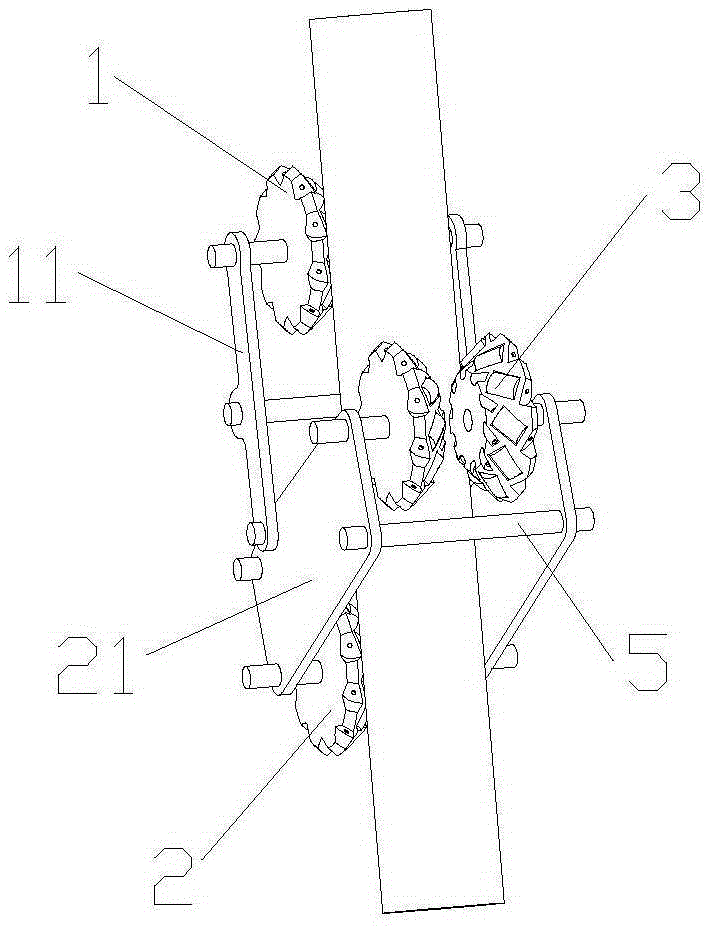
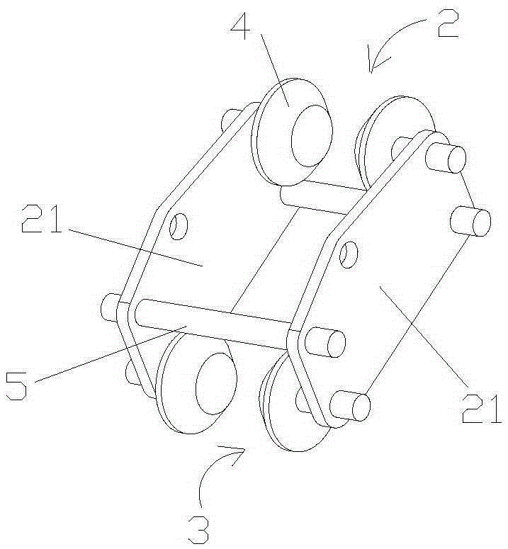
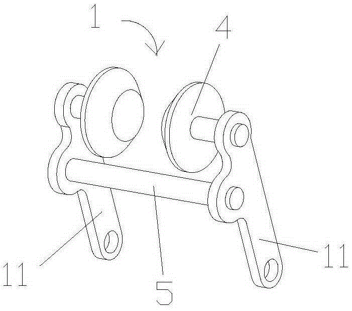
The invention discloses a rotation-controlled high altitude cable robot climbing mechanism. The rotation-controlled high altitude cable robot climbing mechanism comprises three driving components and obstacle sensing devices, wherein the obstacle sensing devices are fixedly arranged at the tops and / or bottoms of the three driving components; each driving component comprises two rollers; the two rollers in each driving component are driving wheels; each roller is conical; one side, in contact with a cable, of each roller, is provided with a roller frame; and a plurality of rolling columns are uniformly arranged in a circumferential direction of each roller frame. After the structure is adopted, a robot climbs when rotating in the same direction; the robot does not climb and rotates around the center of the cable at an angular velocity in a controllable way when rotating in a reverse direction. In addition, during climbing cables with different outer diameters, the posture of the mechanism is invariable, can keep constant spring force, can adapt to different cable diameters and shows strong obstacle crossing capacity. Meanwhile, the rotation-controlled high altitude cable robot climbing mechanism disclosed by the invention has the advantages of small part number, compact structure, light weight and convenient control and mounting.

Description

technical field [0001] The present invention relates to a cable-stayed bridge cable detection robot, in particular to a robot for detecting faults in cables of long-span cable-stayed bridges or other high-altitude poles and transmission lines, in particular to a rotating Controllable high-altitude cable robot climbing mechanism. Background technique [0002] The robots in the prior art are all uncontrollable in the degree of freedom of rotation, so the detection of the entire outer cylindrical surface cannot be completed. [0003] In addition, most of the existing robots have complex structures, heavy weight, weak climbing ability, and weak ability to overcome obstacles. It is troublesome to adjust when adapting to different pipe diameters. For example, when the pipe diameter is different, the posture of the mechanism is different, and the elongation length of the spring is different. , in order to ensure the constant pressing force of the roller, the spring needs to be rep...

Claims


Application Information

Patent Timeline
IPC IPC(8): E01D19/10E01D22/00
Inventor 徐丰羽蒋国平申景金
Owner NANJING UNIV OF POSTS & TELECOMM
Learn More