Unlock instant, AI-driven research and patent intelligence for your innovation.

Linkage Assembly for Implement System of Machine

A technology of linkage components and tools, applied in mechanically driven excavators/dredgers, earth movers/shovels, manufacturing tools, etc., can solve the problems of regular inspection of early cracks and expensive solutions

Inactive Publication Date: 2016-02-03
CATERPILLAR INC
View PDF6 Cites 0 Cited by
  • Summary
  • Abstract
  • Description
  • Claims
  • Application Information

AI Technical Summary

Problems solved by technology

To reduce this stress a third member spanning between the lateral members is usually provided as an internal baffle whose internal welds can fail without warning as they cannot be regularly checked for incipient cracks
The whole nose could be one casting and the third member an integral part of that casting, but this solution would be expensive

Method used


Image

  • Linkage Assembly for Implement System of Machine
  • Linkage Assembly for Implement System of Machine
  • Linkage Assembly for Implement System of Machine

Examples


Embodiment Construction

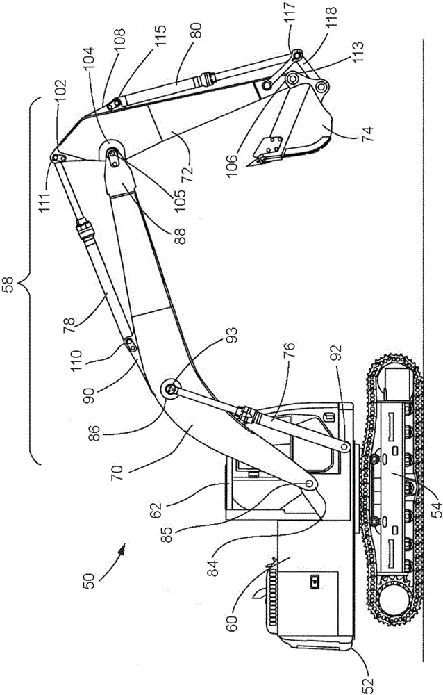
[0031] 31. The present invention relates generally to a linkage assembly for a machine configured for use with an implement system. In an embodiment, the invention relates to a load bearing member for a linkage assembly of an implement system, such as a boom and a boom or stick. The load bearing member includes a body and a joint assembly.

[0032] 32. In an embodiment, the body includes a pair of side walls, a top and a bottom. The sidewalls are in a laterally spaced relationship to one another. The side walls each include an inner surface in facing relationship with each other and an outer surface in corresponding facing relationship with the inner surface. Each side wall defines a pivot opening therein. A top and a bottom extend between the side walls and are joined to the inner surface of each side wall by a welding operation. The sidewalls, top and bottom define a lumen.

[0033]33. In an embodiment, the body is substantially free of structural welds disposed within ...


PUM


Abstract

The invention relates to a load-bearing member for a linkage assembly of an implement system including a body and a joint assembly. The body includes a pair of sidewalls, a top portion, and a bottom portion. The top and bottom portions extend between the sidewalls and are connected to an inner surface of each of the sidewalls. The body is substantially free of structural weldments disposed within an interior cavity of the body. The joint assembly includes a cylindrical tube and a reinforcement plate. The cylindrical tube extends between and is connected to the sidewalls. The reinforcement plate is connected to an outer surface of one of the sidewalls. The reinforcement plate includes a central portion defining a tube opening and is in circumscribing relationship with the cylindrical tube such that it is disposed within the tube opening.

Description

technical field [0001] 1. This patent disclosure relates generally to an implement carrying linkage assembly for a machine, and more particularly to a linkage assembly including a boom and stick for use in a machine such as an excavator. Background technique [0002] 2. Implement bearing linkages for excavators and other similar machines may comprise a multiple load bearing structure made of steel plates joined together by welding to form a box beam (also called a box section), Examples include the components commonly known as "booms" and "sticks." Box girders consist of hollow areas enclosed by steel plates. The box beam structure is subjected to significant torsional loads during the use of the machine, which can deform the box beam structure and lead to failure of the component. [0003] 3. One solution to provide increased rigidity to torsional loaded box girder structures is to weld baffles at various locations within the box girder. However, manufacturing a box gird...

Claims


Application Information

Patent Timeline
Patent Type & Authority Applications(China)
IPC IPC(8): E02F3/38
CPCB23K31/02B23K2101/006B23K2101/24B23K2101/28E02F3/38E02F3/384
Inventor W·J·乌尔里希N·利乌B·阿帕拉T·因图里
Owner CATERPILLAR INC