Supercharge Your Innovation With Domain-Expert AI Agents!

Flow guide plate capable of reducing airflow resistance

A technology of airflow resistance and deflector, used in engine components, machines/engines, mechanical equipment, etc., can solve the problems of increased exhaust pressure of low-pressure cylinders, inability to reduce exhaust pressure, large flow resistance, etc. Steam pressure, simple structure, the effect of reducing flow resistance

Inactive Publication Date: 2016-02-03
XIAN XIELI POWER TECH
View PDF5 Cites 2 Cited by
  • Summary
  • Abstract
  • Description
  • Claims
  • Application Information

AI Technical Summary

Problems solved by technology

The common deflector is a single curved steel plate or straight plate. When this kind of deflector is used, the kinetic energy of the exhaust steam of the low-pressure cylinder is converted into pressure energy, and then the flow deflects, and at the same time, a vortex is generated on the back of the deflector, which has a huge flow. The resistance characteristics make the exhaust pressure of the low-pressure cylinder increase. Although this type of deflector can guide the deflection of the airflow, it cannot reduce the exhaust pressure. Therefore, it is necessary to invent a deflector that has lower flow resistance and also Guided airflow deflection

Method used


Image

  • Flow guide plate capable of reducing airflow resistance
  • Flow guide plate capable of reducing airflow resistance

Examples


Embodiment 1

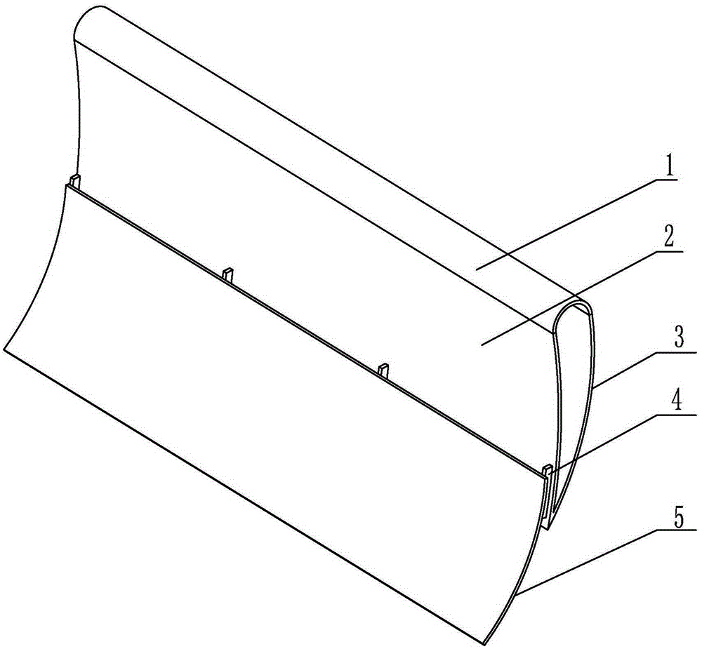
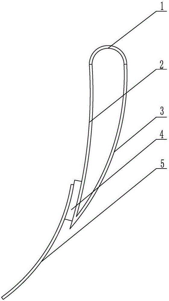
[0014] exist figure 1 , 2 Among them, the deflector for reducing airflow resistance in this embodiment is composed of a blunt head 1 , a pressure side arc plate 2 , a suction side arc plate 3 , a rib plate 4 , and an arc plate 5 .

[0015] In this embodiment, the front end of the blunt head 1 is in contact with the upper end of the pressure side arc plate 2, the blunt head 1 is tangent to the outer contour of the pressure side arc plate 2, and the rear end of the blunt head 1 is in contact with the suction side. The upper end of the arc plate 3 is kissed, the blunt head 1 is tangent to the outer contour of the suction side arc plate 3, the lower end of the pressure side arc plate 2 is kissed with the lower end of the suction side arc plate 3, the geometry of the blunt head 1 The shape is semicircular with a radius of 54mm; the geometric shape of the pressure side arc plate 2 is circular arc with a radius of 1348mm and a central angle of 20°; the geometric shape of the suction...

Embodiment 2

[0017] In this embodiment, the geometric shape of the blunt head 1 is a semicircle with a radius of 38 mm; the geometric shape of the pressure side arc plate 2 is circular arc with a radius of 1250 mm and a central angle of 14°; The geometric shape is arc-shaped, the radius is 600mm, and the central angle is 39°. The geometric shape of the arc plate 5 is arc-shaped, the radius is 490mm, and the central angle is 40°. The pressure side arc plate 2 and the suction side arc plate 3 The center of circle of is positioned at the same side; All the other parts and the connection relation of parts are identical with embodiment 1.

Embodiment 3

[0019] In this embodiment, the geometric shape of the blunt head 1 is a semicircle with a radius of 66.5 mm; the geometric shape of the pressure side arc plate 2 is circular arc with a radius of 1450 mm and a central angle of 22°; the suction side arc plate 3 The geometric shape of the arc plate is arc-shaped with a radius of 750mm and a central angle of 47°. The geometric shape of the arc plate 5 is arc-shaped with a radius of 530mm and a central angle of 50°. The pressure side arc plate 2 and the suction side arc plate The center of circle of 3 is positioned at the same side; All the other parts and the connection relation of parts are identical with embodiment 1.


PUM


Abstract

Disclosed is a flow guide plate capable of reducing airflow resistance. A pressure side arc plate is arranged at one end of a round blunt head, a suction side arc plate is disposed at the other end of the round blunt head, the lower end of the pressure side arc plate is connected with the lower end of the suction side arc plate, and an arc plate is arranged on the front surface of the pressure side arc plate through a rib plate. The flow guide plate capable of reducing airflow resistance is simple in structure, reasonable in design and applicable to the throat part of a condenser and reduces exhaust steam pressure of a low pressure cylinder of a steam turbine.

Description

technical field [0001] The invention belongs to the technical field of steam turbine equipment or devices, and in particular relates to a deflector capable of reducing air flow resistance. Background technique [0002] The throat of the condenser of the power station is used as an important connection part of the cold end equipment of the steam turbine. The exhaust steam of the low-pressure cylinder is discharged to the heat exchange tube bundle of the condenser through the throat of the condenser to condense, and the distribution of the steam flow rate in the throat section of the condenser is extremely uneven, and the uneven steam distribution flow field directly affects the overall heat exchange tube bundle of the condenser Heat transfer performance. In order to improve the heat transfer performance of the condenser tube bundle and increase the vacuum of the unit, deflectors are often installed in the throat of the condenser to interfere with the steam flow, so that the s...

Claims


Application Information

Patent Timeline
Patent Type & Authority Applications(China)
IPC IPC(8): F01D25/24
Inventor 窦春勇樊东朱广宇
Owner XIAN XIELI POWER TECH
Features
  • R&D
  • Intellectual Property
  • Life Sciences
  • Materials
  • Tech Scout
  • Unparalleled Data Quality
  • Higher Quality Content
  • 60% Fewer Hallucinations
Learn More