

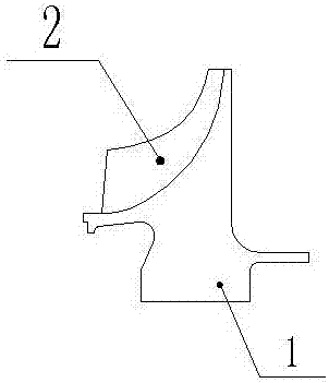
hollow centrifugal impeller
A centrifugal impeller, hollow technology, which is applied to the components of pumping devices for elastic fluids, non-variable volume pumps, machines/engines, etc. Improve bearing capacity, ensure strength and reduce weight
- Summary
- Abstract
- Description
- Claims
- Application Information
AI Technical Summary
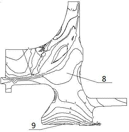
Problems solved by technology
Method used
Image

Examples
Embodiment Construction
[0028] The embodiments of the present invention will be described in detail below with reference to the accompanying drawings, but the present invention can be implemented in many different ways defined and covered by the claims.
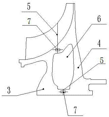
[0029] Such as image 3 As shown, this embodiment provides a hollow centrifugal impeller. The hollow centrifugal impeller in this embodiment is used in a gas turbine engine. One side of the centrifugal impeller has a higher temperature and the other side has a lower temperature. The centrifugal impeller Divided into two parts, the part near the low temperature side uses metal material A3, and the part near the high temperature side uses metal material B4; the split plane 5 is perpendicular to the axis of the centrifugal impeller, such as image 3 As shown, the two split surfaces 5 divide the impeller into two parts, metal A3 and metal B4; the materials of metal A3 and metal B4 are not the same material, and according to the working conditions of the...
PUM
 Abstract
Description
Claims
Application Information