Vehicle lamp design method

A design method and technology for vehicle lights, applied to headlights, road vehicles, vehicle parts, etc., can solve the problems of manpower and time, and achieve the effect of improving uniformity and reducing the number of LEDs

Active Publication Date: 2018-12-21
HYUNDAI MOBIS CO LTD
View PDF5 Cites 0 Cited by
  • Summary
  • Abstract
  • Description
  • Claims
  • Application Information

AI Technical Summary

Problems solved by technology

[0004] However, the existing design method that can improve the light uniformity of the FDT surface light source is carried out through countless trial and error, requiring a lot of manpower and time.

Method used


Image

  • Vehicle lamp design method
  • Vehicle lamp design method
  • Vehicle lamp design method

Examples


Embodiment Construction

[0025] The existing design method capable of improving the light uniformity of the FDT surface light source is performed through countless trial and error, and thus requires a lot of manpower and time. The present invention provides a formulaic optimal design method for vehicle lamps that can solve this technical problem.

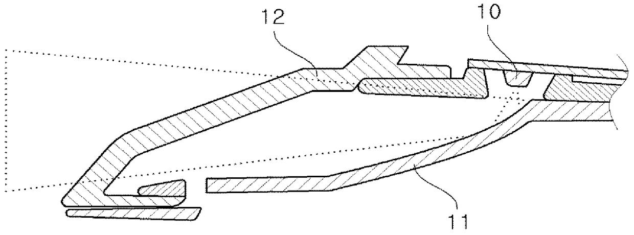
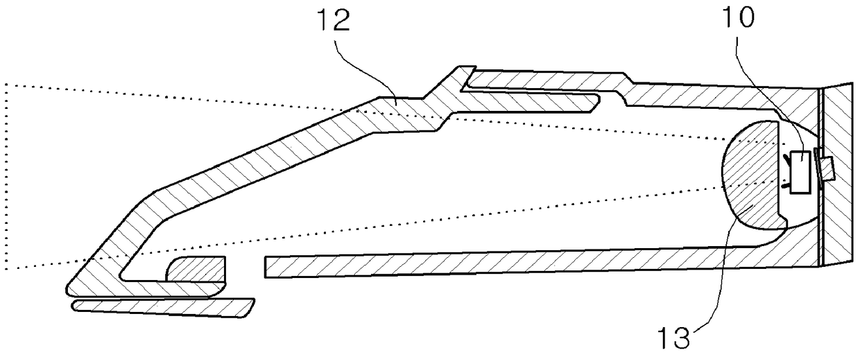
[0026] A method of designing a lamp for a vehicle according to the present invention will be described below with reference to the drawings.

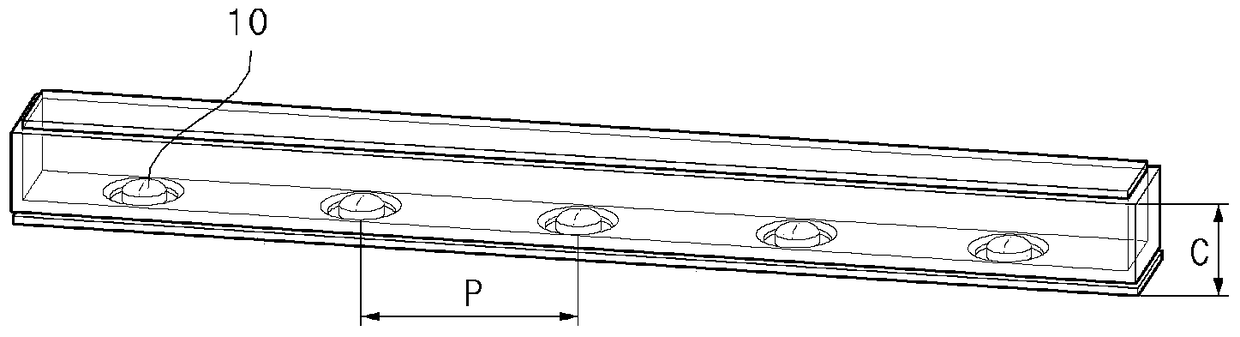
[0027] image 3 is a schematic diagram showing spaces and gaps between light sources according to a preferred embodiment. refer to image 3 , the light uniformity of FDT is a function of the spacing (PITCH) and gap (AIR GAP) between LEDs. To improve specific light uniformity, a proper combination of the two variables, spacing P and gap C, is required. Through this correlation, light uniformity can be improved, and the number of light sources 10 such as LEDs can be reduced. The present invention actually verifies...


PUM


Abstract

The invention relates to a design method for a vehicle lamp. The feature of the invention is to functionalize the interval and gap between the light sources and apply it to the design, so as to improve the uniformity of light. The invention can provide the optimal design scheme of the FDT surface light source lamp. According to the invention, the uniformity can be improved and the number of LEDs can be reduced; the trial and error for improving the light uniformity of the FDT surface light source can be greatly reduced.

Description

technical field [0001] The present invention relates to a vehicle lamp design method, in particular to a vehicle lamp design method capable of providing an optimal design scheme for a fluorescent discharge tube (FDT) surface light source lamp. Background technique [0002] Generally, the light emission method of vehicle lamps can be classified into a reflective type or an indirect type with a general structure, and a direct type with a fluorescent discharge tube (FDT) structure. [0003] Such as figure 1 In the case of the reflection type or the indirect method shown, there are disadvantages such as loss of light from light sources 10 such as light-emitting diodes (LEDs) due to secondary reflection, reduction in light efficiency, and the need for a large number of LEDs to improve light uniformity. Such as figure 2 The direct light type shown has the advantages of increasing light uniformity and reducing the number of LEDs because the light source 10 such as LED does not u...

Claims


Application Information

Patent Timeline
Patent Type & Authority Patents(China)
IPC IPC(8): F21S41/10F21S43/10F21V19/00F21W107/10F21Y113/20
CPCF21Y2103/10F21Y2115/10F21S43/14F21S43/15F21K9/90F21S41/12
Inventor 李赫民
Owner HYUNDAI MOBIS CO LTD
Why Eureka
Try Eureka