Frequency changer cooling and dehumidification system, frequency conversion type compressor unit and refrigeration plant

A frequency converter and cooling flow path technology, applied in the field of refrigeration equipment, can solve problems such as insufficient cooling of reactance modules, and achieve the effect of ensuring safe and reliable operation and avoiding insufficient cooling

Active Publication Date: 2016-02-03
GREE ELECTRIC APPLIANCES INC
View PDF6 Cites 8 Cited by
  • Summary
  • Abstract
  • Description
  • Claims
  • Application Information

AI Technical Summary

Problems solved by technology

[0009] The purpose of the present invention is to provide a frequency converter cooling and dehumidification system, frequency conversion compressor unit and refrigeration

Method used


Image

  • Frequency changer cooling and dehumidification system, frequency conversion type compressor unit and refrigeration plant
  • Frequency changer cooling and dehumidification system, frequency conversion type compressor unit and refrigeration plant
  • Frequency changer cooling and dehumidification system, frequency conversion type compressor unit and refrigeration plant

Examples


no. 1 example

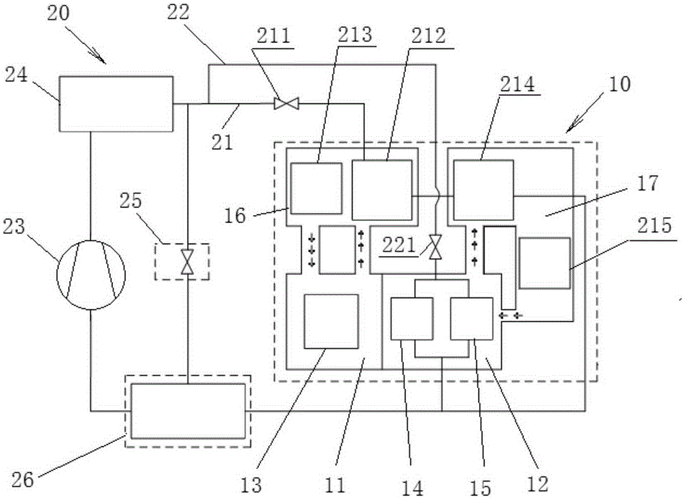
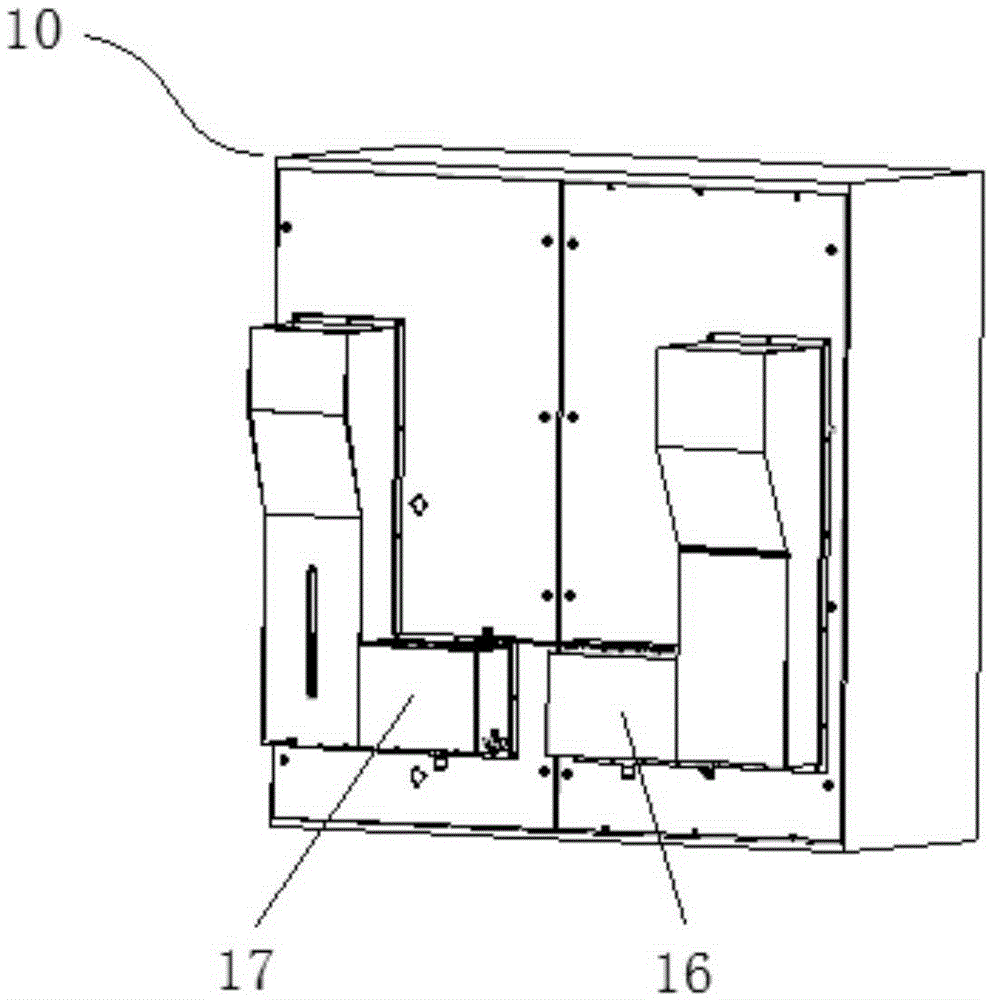
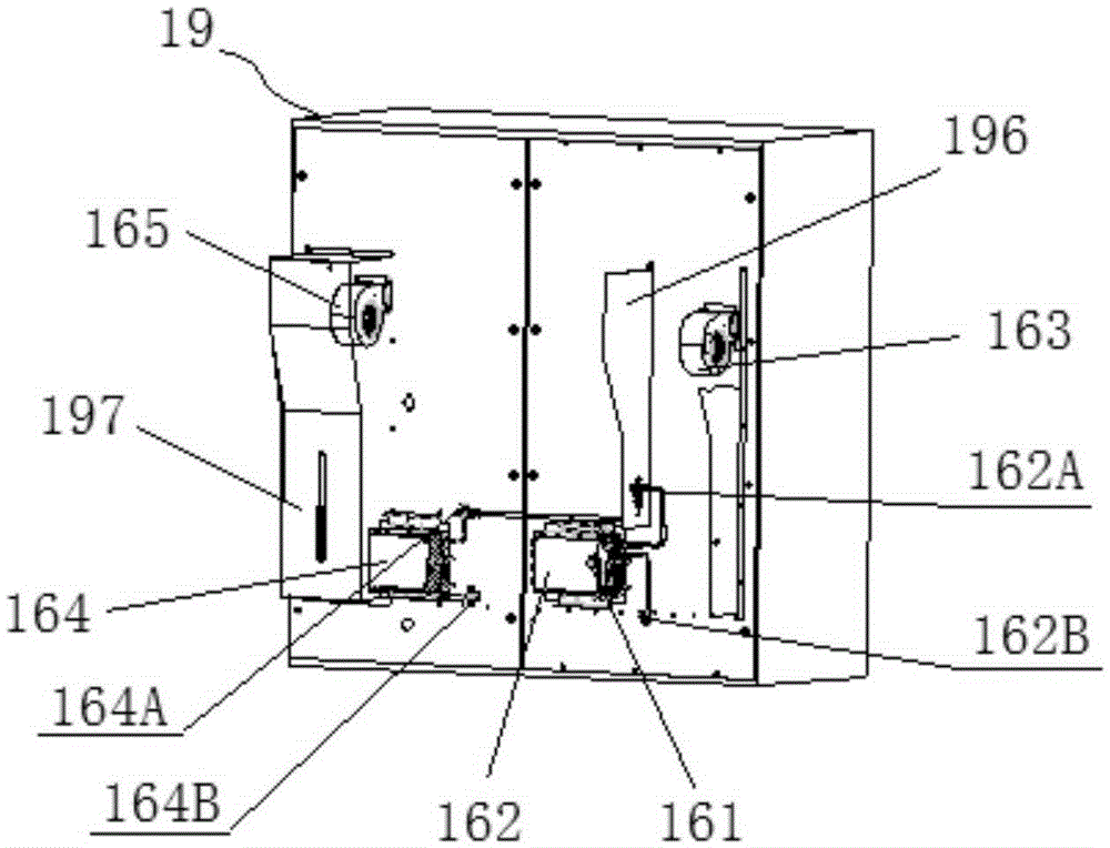
[0076] figure 1 It is a schematic diagram of the principle of the inverter cooling and dehumidification system according to the first embodiment of the present invention. figure 2 It is a structural schematic diagram of the frequency converter involved in the frequency converter cooling and dehumidification system according to the first embodiment of the present invention. image 3 It is a structural schematic diagram of the inverter cooling and dehumidification system and related inverters in the first embodiment of the present invention after removing part of the air duct wall plates in the first air duct and the second air duct. Figure 4 for image 3 Schematic diagram of the partially enlarged structure.

[0077] Such as Figure 1 to Figure 4 As shown, in this embodiment, the inverter 10 targeted by the inverter cooling and dehumidification system has a first space 11 and a second space 12 that are isolated from each other. The frequency converter includes a reactance...

no. 2 example

[0106] Figure 5 It is a schematic diagram of the principle of the inverter cooling and dehumidification system according to the second embodiment of the present invention, where the third cooling flow path connected to the inverter module and the main refrigeration circuit connected to the third cooling flow path are not shown. Image 6 It is a schematic schematic diagram of the inverter cooling and dehumidification system according to the second embodiment of the present invention, in which only the third cooling flow path connected to the inverter module and the main refrigeration circuit connected to the third cooling flow path are shown.

[0107] Such as Figure 5 with Image 6 As shown, in the second embodiment, the frequency converter 10 has a first space 11 and a second space 12 that are isolated from each other. The frequency converter includes a reactance module 13 , a rectification module 14 and an inverter module 15 . The reactance module 13 has a hot surface, a...


PUM


Abstract

The invention discloses a frequency changer cooling and dehumidification system, a frequency conversion type compressor unit and a refrigeration plant. The frequency changer cooling and dehumidification system is used for conducting cooling and dehumidification on a frequency changer; the frequency changer has a first space and a second space which are isolated, a reactance module is arranged in the first space, and a rectifier module and an inversion module are arranged in the second space; the reactance module is provided with a hot surface, and the rectifier module and the inversion module are each provided with a cold surface; and the frequency changer cooling and dehumidification system comprises a first cooling fluid passage, and the first cooling fluid passage comprises a first heat exchanger and a second heat exchanger, wherein the first heat exchanger is used for cooling the first space, and the second heat exchanger is used for conducting dehumidification on the second space. According to the technical scheme, the problem of insufficient cooling of a reactance module in a frequency changer external air forced circulation scheme can be effectively solved, and safe and reliable running of the frequency changer is better guaranteed.

Description

technical field [0001] The invention relates to the technical field of refrigeration equipment, in particular to a frequency converter cooling and dehumidification system, a frequency conversion compressor unit and refrigeration equipment. Background technique [0002] For refrigeration equipment with variable-frequency compressor units, such as high-power variable-frequency centrifugal chillers, the key components such as the reactance module, rectifier module, and inverter module of the frequency converter of the variable-frequency compressor unit accumulate and work with the working time during use. The increase of the load generates a lot of heat, so effective cooling is required to ensure that the inverter works in a reliable temperature range. [0003] In the prior art, the refrigerant of the main refrigeration circuit of the refrigeration equipment or the refrigerant provided by the external compression condensing unit is usually used to enter the cooling space inside...

Claims


Application Information

Patent Timeline
IPC IPC(8): F25B1/00H02M1/00
Inventor 刘贤权周宇潘翠万亮胡超常易海洋周堂金成召刘魏
Owner GREE ELECTRIC APPLIANCES INC
Why Eureka
Try Eureka