System and method for measuring content based on fuzzy logic

A fuzzy logic algorithm, fuzzy logic technology, applied in the system field of content

Active Publication Date: 2016-02-03
ROSEMOUNT TANK RADAR
9 Cites 0 Cited by

AI-Extracted Technical Summary

Problems solved by technology

In particular, three-dimensional rendering of the upper surfac...

Method used

[0129] The fuzzy logic module 20 may apply one or more fuzzy logic algorithms, which cont...

Abstract

The invention provides a system and a method for measuring the content based on fuzzy logic. A method, a non-transient computer readable medium and system comprise a fuzzy logic module arranged to be used for responding to a received echo receiving from a receiver. By applying a fuzzy logic algorithm, the confidence level of an origin of the received echo is calculated. The received echo is reflected or scatted from the origin. The method, the non-transient computer readable medium and system comprise a volume calculator arranged to be used for responding to (a) the estimated position of the origin and responding to (b) the confidence level of the origin in order to calculate the volume of the content.

Application Domain

Volume measurement apparatus/methods

Technology Topic

CalculatorData mining +3

Image

  • System and method for measuring content based on fuzzy logic
  • System and method for measuring content based on fuzzy logic
  • System and method for measuring content based on fuzzy logic

Examples

  • Experimental program(1)

Example Embodiment

[0056] In the following detailed description, numerous specific details are set forth in order to provide a thorough understanding of the present invention. However, it will be understood by those skilled in the art that the present invention may be practiced without these specific details. In other instances, well-known methods, procedures, and components have not been described in detail so as not to obscure the present invention.
[0057] The subject matter which is regarded as the invention is particularly pointed out and distinctly set forth at the conclusion of the specification. However, the invention, as to its organization and method of operation, together with its objects, features and advantages, is best understood by reading and referring to the following detailed description when read in conjunction with the accompanying drawings.
[0058] It will be understood that, for simplicity and clarity of illustration, elements shown in the figures have not necessarily been drawn to scale. For example, the dimensions of some of the elements may be exaggerated relative to other elements for clarity. Further, where considered appropriate, reference numerals may be repeated among the figures to indicate corresponding or analogous elements.
[0059] Any reference to a system in the specification shall apply to the methods executable by the system.
[0060] Because most of the described embodiments of the invention can be implemented using electronic components and circuits well known to those skilled in the art, in order to understand and appreciate the basic concepts of the invention, and in order not to obscure or obscure the teaching of the invention, details will be omitted will be explained at greater length unless deemed necessary as stated above.
[0061] Any reference to a method in the specification shall apply to a system that can perform the method, and to a non-transitory computer-readable medium that stores instructions that, once executed by a computer, cause performance of the method.
[0062] Any reference to a system in the specification shall pertain to a method executable by the system, shall pertain to a non-transitory computer-readable medium storing instructions that, once executed by a computer, cause performance of the method.
[0063] The present invention is a system for measuring the quantity of material stored in a silo such as a silo, open silo, dome or the like. In particular, the invention can be used to monitor inventory in silos.
[0064] The principles and operation of content measurement according to the present invention may be better understood with reference to the drawings and corresponding descriptions.
[0065] A bin contains an unknown amount of content—eg, a solid content that forms an unknown three-dimensional shape. For example, in a cylindrical bin with a single filling point at the top, the contents may be packed into a cone. It is assumed that the topography of the upper surface and the dimensions of the bin determine the volume of solid material within the bin.
[0066] The term echo means a radiation signal received by a receiver and scattered or reflected from an object due to the transmission of the radiation pulse.
[0067] The term "origin" refers to the source of the echo—referring to the receiver's estimate of where the echo is reflected, scattered, or otherwise directed to the receiver.
[0068] The terms echo and origin are used interchangeably in this specification.
[0069] Corresponding echoes are echoes that share the same (or substantially the same) origin.
[0070] The terms "list" and "database" are non-limiting examples of data structures and are used interchangeably.
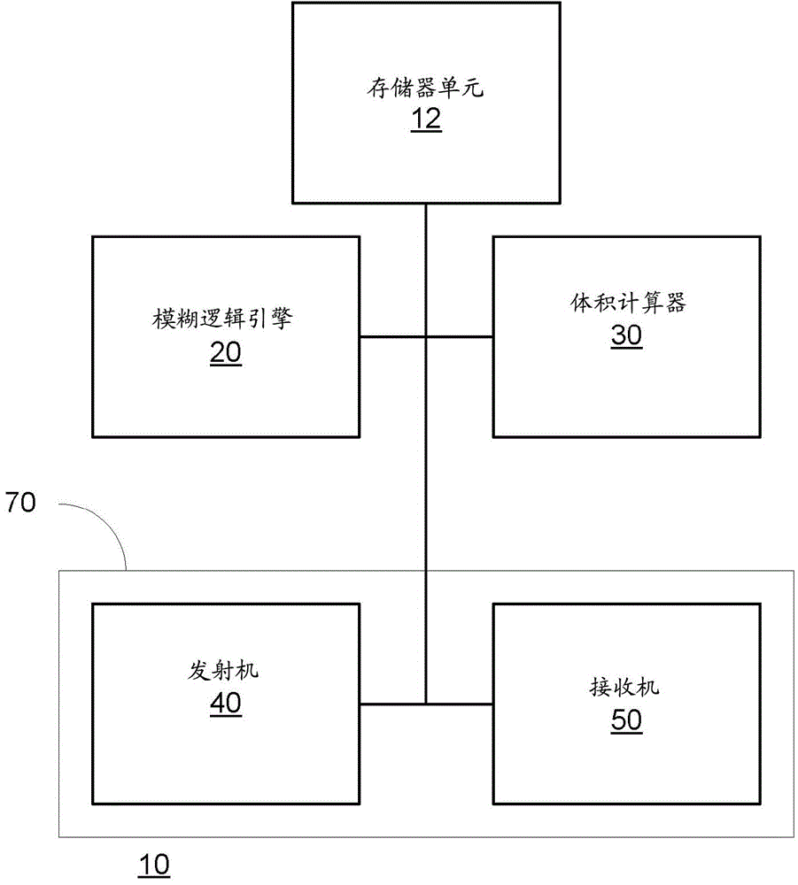
[0071] figure 1 A system 10 according to one embodiment of the invention is shown.
[0072] System 10 includes fuzzy logic module 20 , memory unit 12 and volume calculator 30 . These modules may belong to (or may form) a computer system.
[0073] figure 1 System 10 is illustrated also including receiver 50 and transmitter 40 . The transmitter 40 and the receiver 50 form a transceiver 70 . Notably, the inclusion of any of these components within system 10 is optional.
[0074] Transmitter 40 may transmit radiation pulses over multiple time periods. The radiation pulses may be radio frequency pulses, acoustic pulses, or the like.
[0075] Receiver 50 may receive received echoes resulting from the transmission of the radiation pulse.
[0076] Acoustic energy pulses may be wide enough to cover a relatively large area of ​​the upper surface of the contents without scanning—compared to the much narrower area that can be covered by narrow-section radio frequency or narrow-section (approximately 10 degree aperture) ultrasound . It is worth noting that the present invention is applicable to large (approximately 60-80 degree aperture) cross section RF pulses (eg 1 GHz RF pulses) or scanning systems using RF or scanning systems using ultrasound. The acoustic energy pulses may have a frequency between 2-7 Hertz.
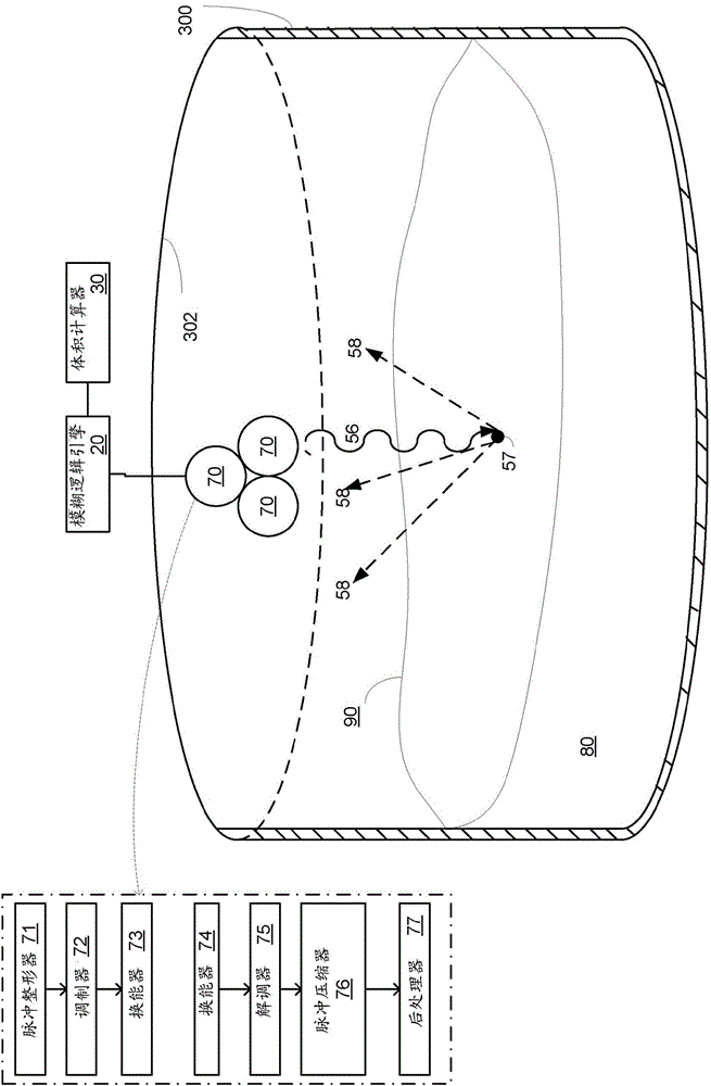
[0077] figure 2 is a partial cross-sectional view of a silo 300 with an upper surface 90 of the system 10 mounted on the ceiling 302 of the silo 300 and facing the contents, according to one embodiment of the invention.
[0078] ( figure 1 In) the transmitter 40 and the receiver 50 are realized by three non-collinear acoustic transceivers 70. A non-limiting example of such an acoustic transceiver is shown in US Patent 8,091,421, which is incorporated herein by reference. It is worth noting that the number of transceivers can be different from three, and radio frequency and ultrasonic radiation can be used.
[0079] Each acoustic transceiver 70 may include a transmit path and a receive path. The transmit path may include a pulse shaper 71, modulator 72, and transducer (speaker) 73 while the receive path may include a transducer (microphone) 74, demodulator 75, pulse compressor 76, and postprocessor 77, as in is shown in US Patent Application Serial No. 13/041461, filed July 3, 2011, entitled "Variable length thranging and direction-finding signals constructed from beam limited kernels and sparse spreading sequences", which is incorporated herein by reference.
[0080] A pulse shaper 71 generates baseband pulses from the core. Modulator 72 modulates the carrier with baseband pulses. The transducer 73 emits the modulated carrier wave as transmitted acoustic pulses 56 towards the upper surface 90 of the contents to the medium supporting the propagation of the carrier wave.
[0081] The echo 58 is reflected from the echo origin 57 of the upper surface 90 and received by the transducer 74 . Demodulator 75 demodulates the echoes to provide a representation of the received baseband pulses.
[0082] Pulse compressor 76 compresses the representation of the baseband pulses by deconvolution. Pulse compression provides compressed pulses that are time-shifted representations of the original kernel. Post-processor 77 applies post-processing to the compression pulse and extrapolates the extent of points of upper surface 90 as half the result of the round-trip travel time of acoustic pulse 56 and echo 58 .
[0083] Directional information is obtained by transmitting acoustic pulses and receiving echoes using different combinations of transceivers 70 .
[0084] One or more transceivers 70 may operate as transmitters at any given point in time and may emit pulses of acoustic energy (acoustic pulses) 56 toward the upper surface 90 of the contents 80 of the chamber 300 .
[0085] Sonic pulse 56 at figure 2 is symbolized as a waveform emerging from a transceiver 70. The echo of the acoustic pulse 56 reflected from the upper surface 90 back to the transceiver 70 is given by figure 2 Arrow 58 in indicates.
[0086] The echoes 58 received by the transceiver 70 operating as a receiver 50 may in turn generate a detection signal representative of the shape of the upper surface 90 of the content 80 .
[0087] The detection signal may be responsive to the time of arrival of the echoes, the relationship between the arrival times of the echoes at different transceivers, and the spatial layout of the transceivers.
[0088] Echoes will typically originate from large surfaces, irregular areas on the upper surface, and silo sidewalls where material touches the wall creating corners. The system will acquire echoes one after the other, separated in time according to the extent of the system's distance from the origin of each echo.
[0089] Assuming each time an echo is received, system 10 (eg, receiver 50 ) may generate an estimate of the range of origin of the received echo (based on the time of arrival TOA) and the direction of arrival (DOA) of the received echo.
[0090] can be used, for example, with multiple receivers (or such as figure 2 The three transceivers 70 of the transceiver), and apply a triangulation-based method (or other direction-location method) to detect the direction of each echo to obtain the DOA.
[0091] The bin is assumed to be a noisy environment and the accuracy of range and DOA estimation depends on the noise. Furthermore, the spacing between received echoes is determined by the range resolution of the system and may result in additional errors in the estimated direction.
[0092] The signal-to-noise ratio (SNR) of the received echoes is represented by the SNR attribute, which may vary over time. The SNR may be a function of the geometry of the echo origin and depends on the dust concentration in the air at the time of measurement. The dust concentration may vary over time (for example, typically after filling the air will have more dust than after a few hours). Therefore, signal strength may vary over time. Noise is usually caused by external noise sources, such as by machinery in the vicinity of the chamber that may generate acoustic or electromagnetic energy.
[0093] In addition to meaningful echoes from the material, the system may get false echoes due to multipath trajectories. Figure 8Shown is a cross-section of a silo 300 storing the contents 80 , the transceiver 70 of the system irradiating a point 57 on the upper surface 90 of the contents 80 with a pulse of radiation 56 . Point 57 reflects the echo of radiation pulse 56 towards the left wall of silo 300 (path 58 ( 1 )) and the left wall reflects the echo (path 58 ( 2 )) towards transceiver 70 .
[0094] Point 57 is the true origin of echo 58, but due to multipath, the transceiver "sees" a false origin 55 located outside of bin 300 - DOA at path 58(2) but at equal paths 58(1) and 58 (2) at the distance (from transceiver 70) of the sum.
[0095] Based on its relatively large distance outside the silo 300, the system can determine that the false origin 55 is not the true origin of the echo. The system can also apply a fuzzy logic algorithm to the origin 55 of the error and reduce the confidence level of the received echo 58 in relation to the origin of the error.
[0096] Using pulses of other frequencies, multipath can additionally or alternatively be detected through the radiation spot 57 - where multipath might be expected to result in different received echoes.
[0097] The system 10 may detect false echoes and such false echoes should not be included in the final content volume estimate.
[0098] In addition to the above (locations outside the silo environment), the system can detect false echoes by detecting an angle between the origin of a received echo and the origin of another received echo greater than the maximum content slope.
[0099] False echoes can also be detected by changing the angle of illumination to the same area, directing a radiation pulse with zero energy (or very low energy) at the origin of the received echo, and receiving an echo with a lot of energy.
[0100] It is expected that the "true" origin of the echo can also be seen at other perspectives such as at transitions between different frequencies or different beam inclinations. Echoes whose origin is not verified by other viewing angles may be considered false echoes and may receive a lower confidence level.
[0101] Dust and noise sources can modify the magnitude (temporarily canceling the echo from the scanner) and direction of each echo.
[0102] Volume readings from system 10 should be immune to fluctuations in dust concentration and noise. Variations in noise or dust levels from machinery outside the silo should not create fluctuations in reported volume levels.
[0103] False echoes should be efficiently filtered, resulting in subgroups of echoes that are self-consistent among the members of the group and none of them violate some general rule such as that all echo sources should be inside the bin.
[0104] Echoes with low SNR should be weighted lower than strong echoes with high SNR.
[0105] The system 10 may take multiple measurements at different points in time and is arranged to provide stable measurements over time. The system 10 can take into account various parameters of the reflected echo that may fluctuate even when the volume of the content remains constant. The system 10 is arranged to know the quality of the estimated information from each echo. Since the signal quality/echo source is variable, reliable quality attributes can assist in estimating echo parameters at the best quality signal.
[0106] The system 10 can track received echoes over time, assign confidence levels (using the fuzzing module 20) to the origin of the echoes, dynamically update data structures reflecting reference echoes, and remove reference echoes in a smooth manner (during verification Receive echoes that may come from this origin, but after no such echo has been received during multiple transmit and receive cycles) to provide stable results. A single pulse of radiation can be transmitted during a single transmit and receive cycle.
[0107] The receiver 50 may be arranged to detect peaks (maximum points) of the received echoes and to refer to these peaks when calculating TOA and DOA.
[0108] The volume calculator 30 can be maintained as Figure 7 Various data structures of those shown.
[0109] Figure 7 A database 302 of received echoes is shown, which stores attributes 302(1)-302(J) of received echoes (such as content due to illumination by one or more radiation pulses during one or more transmit and receive cycles). The received echo received by the object).
[0110] Figure 7 Also shown is a reference echo database 310, which stores attributes 310(1)-310(k) of the reference echoes. Reference echoes were received in the past. The properties of the reference echo can be continuously updated over time.
[0111] Figure 7 A list 320 of echoes to be used for volume calculation is also shown. This list 320 may be equal to the reference echo database 310 at the point in time at which the volume was calculated. Additionally, list 320 may differ from reference echo database 310 in that it includes a number of echoes, stores confidence levels instead of attributes, includes more or fewer echoes than included in database 310 , etc.
[0112] The volume calculator 30 may be arranged to update the reference echo property data by adding new reference echoes, deleting existing reference echoes, and changing properties of reference echoes.
[0113] During each transmit and receive cycle, the receiver 50 is arranged to receive one or more received echoes and to identify the maximum point of each pulse.
[0114] Image 6 Three graphs 201 , 202 and 203 are shown according to one embodiment of the invention.
[0115] Diagram 201 includes three received echoes 210, 220 and 230 received by the first transceiver during a first transmit and receive cycle. The graph 202 includes three received echoes 210', 220' and 230' received by the second transceiver during the first transmit and receive cycle. The difference in TOA between received echoes 210 and 210', 220 and 220', and 230 and 230' allows system 10 to calculate the DOA of these received echoes.
[0116] The graph 203 includes three received echoes 212, 222 and 232 received by the first transceiver during the second transmit and receive cycle.
[0117] Image 6 Also shown are the maximum points 211, 221, 231, 211', 221', 231', 213, 223 and 233.
[0118] Each maximum point of the received echo is associated with the origin of the received echo, and the position of the origin is determined by the maximum point (T1, T2, T3, T1', T2', T3' and T4') and the The TOA indicated by the direction of arrival is calculated.
[0119] Received echoes 210 and 212 have substantially the same origin and are considered as corresponding received echoes.
[0120] Received echoes 220 and 222 have substantially the same origin and are considered as corresponding received echoes.
[0121] Graph 203 does not include received echoes 230 . Accordingly, the received echo 230 may be sent to a deletion process. If received echo 244 is not received before the second transmit and receive cycle, received echo 244 may be added to database 310 as a new reference echo.
[0122] The volume calculator 30 is arranged to compare the received echo with a reference echo. If the reference echo database 310 does not include a reference echo corresponding to the received echo (no reference echo having substantially the same origin as the received echo), the received echo may be added to the database 310 and Treated as a new reference echo.
[0123] Reference echoes of the database that are expected to have corresponding received echoes - but such received echoes are not received, are fed to a deletion process that determines whether to delete these reference echoes from the database 310 .
[0124] The erasure process may ignore the absence of corresponding received echoes during transmit and receive periods during which the SNR is too low to receive such corresponding received echoes.
[0125] If only a subset of expected received echoes is received – if only up to M corresponding received echoes are received during N transmit and receive cycles (during which reception parameters facilitate the reception of these received echoes) , the reference echoes may be deleted from the database 310 and/or list 320 during the deletion process, where N exceeds M. M may be zero and N may be three or more.
[0126] Reference echoes with a confidence level of zero (or nearly zero) in database 310 and list 320 may not be removed from list 320 (and/or database 320) if the current SNR is below the minimum SNR at which they may have been detected. 310) Delete.
[0127] Additionally or alternatively, if a reference echo is found to be a false echo, it will be deleted from the list and database 310 .
[0128] review figure 1 , the fuzzy logic module 20 may be arranged to calculate a confidence level for each reference echo and/or received echo. The confidence level may be an attribute of the received echo and/or the reference echo and may be stored in the databases 302 and 310 .
[0129] Fuzzy logic module 20 may apply one or more fuzzy logic algorithms, which contribute to the stability of volume measurements performed by volume calculator 30 .
[0130] A confidence level for an echo may be calculated based on one or more properties of the echo. Attributes may include, for example, at least some of the following:
[0131] a. Signal-to-noise ratio attribute - the energy ratio of signal to noise. Noise is usually measured on separate listen periods.
[0132] b. Constant False Alarm Rate (CFAR) Threshold Attribute - The ratio of the echo energy to the average energy around the echo range.
[0133] c. Properties within the silo - The coordinates of the echo origin are determined from time-of-flight and angle-of-arrival estimates, assuming known silo geometry and scanner location. It is required that the echo source will be within the silo walls (including the floor).
[0134] d. Physical Constraints Attribute - Reflects proximity to physical barriers or other physical constraints that may be relevant to a particular frequency and/or DOA.
[0135] e. Relative Energy Properties - In general, the echo closest to the transceiver (minimum range) should be a direct reflection and thus more reliable as a point of reiteration in the process of establishing a coherent subgroup of echoes. However, in some cases, although the actual material level is far away, there will be a small amount of residual echo at close range due to objects or material buildup in the silo. To solve this problem, the system localizes the strongest echoes, thereby reducing the CL of echoes with significantly (˜×10) lower energy.
[0136] f. Angle Contradictory Properties - The slope of the upper surface of the content is expected to be below the maximum slope value and the slope between origins should be below the maximum slope value.
[0137] Figure 10A linear fuzzy logic function according to one embodiment of the invention is shown. Curves 401-405 represent the application of fuzzy logic functions to various parameters (SNR properties, CFAR properties, out-of-silo properties, relative energy properties, and physical constraints properties, respectively). The x-axis represents the value of the parameter, while the y-axis represents the attribute value.
[0138] According to one embodiment of the invention, if some or all of these properties are fuzzy logic functions, the confidence level of the echo. The fuzzy logic module 30 may set the confidence level of the echo to the minimum of all attributes.
[0139] It is worth noting that each property can be calculated by applying fuzzy logic functions to the corresponding parameters calculated by the receiver 50 or even by the volume estimator itself (SNR, CFAR, relative energy, position with respect to the bin wall, slope ...).
[0140] Angle contradictory estimates can be detected and handled by the following process:
[0141] The received echoes are classified by their extent (distance from origin to receiver).
[0142] Cycle through all possible pairs of origin, each pair having a nearer echo (with confidence level CL1 ) and a distant echo (with confidence level CL2 ).
[0143] Calculate the mutual confidence level (CL_A) for angular contradictions.
[0144] In case of certain angular conflicts (CL_A<1), CL2 can be reduced (proximity range priority).
[0145] CL2 can be reduced proportionally to CL1 and CL2.
[0146] a. B=max((1-CL1), CL_A).
[0147] b. CL2 = min(CL2, B).
[0148] The confidence level of an echo of list 320 may determine the weight assigned to that echo in the calculation of the volume of contents 80 .
[0149] Reference echoes with low confidence levels may be deleted from the database 310 after not being received during a number of transmit/receive cycles during which they should have been received.
[0150] The system 10 can maintain many reference echoes with low confidence levels in the database 310 and list 320 before deletion, and this can lead to improved stability because removal (especially smooth removal) of low confidence level reference echoes will not Will significantly change the volume estimate of the contents.
[0151] According to one embodiment of the invention, the confidence level attribute can only be updated by increasing it over time. Thus, the confidence level attribute value may be kept at a value reflecting the best reception conditions for the reference pulse - eg - a value reflecting the best SNR.
[0152] After preparing the list 320, the volume calculator can estimate the volume of the contents in response to the following formula, in particular it can perform the following calculation:
[0153]
[0154] where "XY area of ​​the bin" denotes the section of the bin along an imaginary XY plane perpendicular to the Z axis, Zi is the height of the ith origin (summed over all origins included in the list 320), and CLi is the height of the ith origin of the list 320 Confidence level for the i-th origin.
[0155] Figure 7 Illustrated is the origin 99 of the upper surface expected to form the contents, and the height of a point (Zi98). List 320 may include all origins 99 or a subset of origins 99 .
[0156] If the XY section of the bin changes with the height of the bin, then the multiplication is replaced by an integral.
[0157]
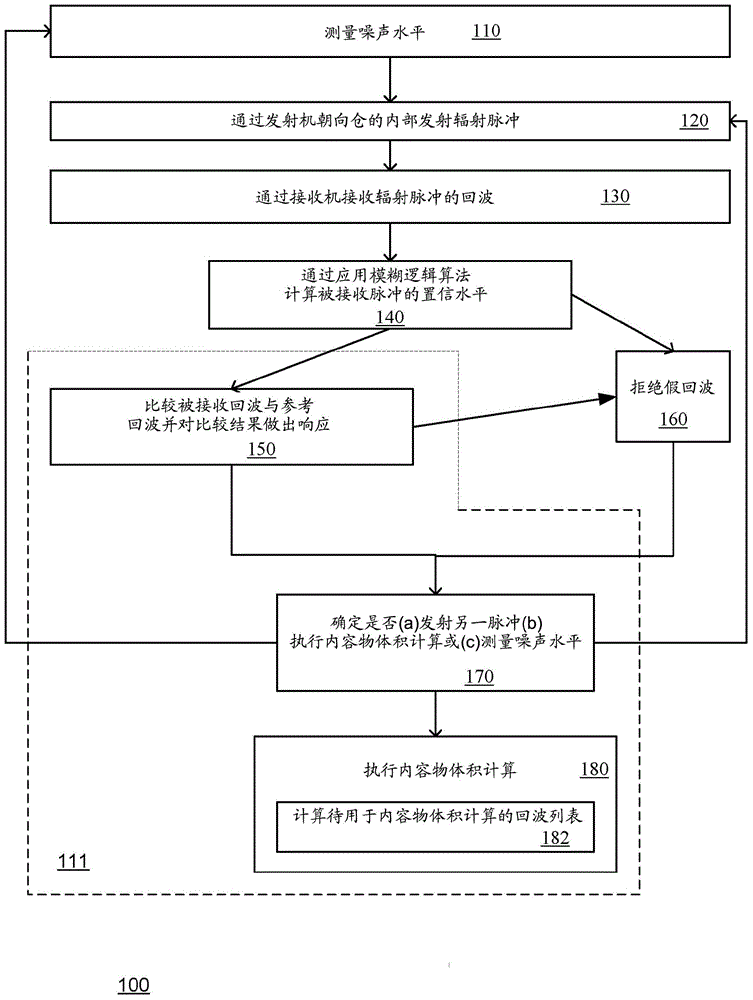
[0158] image 3 A method 100 according to one embodiment of the invention is shown.
[0159] The method 100 may begin with a stage 110 of measuring a noise level. This phase may occur in a cyclical fashion in response to events such as a decrease in SNR. It can be executed every multiple transmit and receive cycles.
[0160] Stage 110 may be followed by stage 120 of emitting a radiation pulse towards the interior of the chamber by the transmitter.
[0161] Stage 120 may be followed by stage 130 of receiving an echo of the radiation pulse by a receiver.
[0162] Stage 130 may include calculating received echo parameters such as SNR, CAFR, position relative to the silo, relative energy, and the like.
[0163] Stage 130 may comprise detecting peaks of the received echoes, calculating the time of arrival and direction of arrival of the peaks of the received echoes.
[0164] Stage 130 may include changing a property of the received echo based on another received echo's property - this may include calculating a relative energy property.
[0165] Stage 130 may be followed by stage 170 and stage 140 of removing false echoes.
[0166] Stage 140 may comprise applying a fuzzy logic algorithm by the fuzzy logic module to calculate a confidence level of the origin of the received echo in response to the received echo; wherein the received echo is reflected or scattered from the origin.
[0167] Stage 140 may include stages 141 , 145 and 146 . Stage 141 is followed by stage 145 , which is followed by stage 146 .
[0168] Stage 141 may comprise applying a fuzzy logic algorithm to calculate properties of the received echoes. Stage 141 may include calculating any of the attributes mentioned in this specification and/or other attributes. Stage 141 is shown as comprising: (a) stage 144, applying a fuzzy logic algorithm to calculate the SNR attribute of the received echo; (b) stage 142, applying a fuzzy logic algorithm to calculate the received echo CFAR attribute; and/or (c ) stage 143, applying a fuzzy logic algorithm to calculate the properties of the physical confinement (eg contained in the bin) of the received echo.
[0169] Stage 145 includes calculating a confidence level of the received echo in response to a property of the received echo.
[0170] Stage 146 may include updating the confidence level of the received echo in response to another property of the received echo. Stage 146 is shown to include: (a) stage 147, applying a fuzzy logic algorithm to the angle formed between the origin of the received echo and the origin of another echo to update the confidence level; and (b) stage 148, A fuzzy logic algorithm is applied to the ratio between the intensity of the received echo and the intensity of the other received echo to update the confidence level.
[0171] Stage 140 may be followed by stage 111, which calculates, by the volume calculator, the volume of the contents in response to (a) the estimated location of origin, and (b) a confidence level of origin.
[0172] Stage 111 may include stages 150 , 160 , 180 and 190 . Stage 170 may be followed by stage 111 .
[0173] Stage 150 may comprise comparing the received echo with a reference echo. The reference echoes may be stored in a data structure such as database 310 .
[0174] Stage 150 may be followed by stage 160 of responding to the comparison result. This may include adding reference echoes to the database, updating properties of reference echoes, and deleting reference echoes from the database.
[0175] Stage 160 may include:
[0176] a. Updating at least one attribute of the reference echo in response to one of the comparison results.
[0177] b. If the result of the comparison shows that the signal-to-noise ratio of the reference echo is lower than the noise ratio of the received echo corresponding to the reference echo, determining to update at least one attribute of the reference echo.
[0178] c. Delete reference echoes from the database of reference echoes associated with origins that do not reflect or scatter received echoes over multiple transmit and receive cycles.
[0179] d. The method of claim 24, comprising deleting the reference echo if the noise level facilitates reception of the received echo from the origin during the plurality of transmit and receive cycles.
[0180] Figure 4 Stage 150 is shown to include stages 151 and 152 , and stage 160 is shown to include stages 161 , 162 and 163 .
[0181] Phase 151 consists in checking whether the received echo has a corresponding reference echo.
[0182] If the answer is in the affirmative (Y), then stage 151 is followed by stage 161, which compares the properties of the received echo and the corresponding reference echo, and based on the comparison, determines whether to update the reference echo characteristics, and updates the reference echo sex (if determined to do so).
[0183] If the answer is no (N), then stage 151 is followed by stage 162, which adds the received echoes to the reference echo database.
[0184] Stage 152 may comprise determining whether a reference echo has a corresponding received echo. If the answer is no, stage 152 may be followed by stage 163, which responds to lack of corresponding echoes, reception history (previous reception of lack of reception of corresponding received echoes) and estimated reception of corresponding received echoes. Echo Capability, determines whether reference echoes are deleted from the reference echo database.
[0185] The present invention can also be implemented with a computer program running on a computer system, comprising at least code portions for performing the steps of the method according to the invention when run on a programmable device such as a computer system, or enabling a programmable device to perform Functionality of the device or system according to the invention.
[0186] A computer program is like a list of instructions for a specific application program and/or operating system. A computer program may, for example, include one or more of the following: subroutines, functions, procedures, object methods, object implementations, executable applications, applets, servlets, source code, object code, shared libraries/dynamic Load libraries, and/or other sequences of instructions designed for execution on a computer system.
[0187] The computer program can be stored internally on a non-transitory computer readable medium. All or part of the computer program may be permanently, removably provided on a computer-readable medium or remotely coupled to an information handling system. Computer readable media may include, for example and without limitation, any number of the following: magnetic storage media, including magnetic disk and tape storage media; optical storage media, such as compact disc media (e.g., CD-ROM, CD-R, etc.) and Digital video disk storage media; non-volatile storage media, including semiconductor-based storage units, such as flash memory, EEPROM, EPROM, ROM; ferromagnetic digital memory; MRAM; volatile storage media, including registers, buffers or high-speed Cache, main memory, RAM, etc.
[0188] A computer process generally includes an executing (running) program or portion of a program, current program values ​​and state information, and resources used by the operating system to manage the execution of the process. An operating system (OS) is software that manages a computer's resource sharing and provides programmers with an interface for accessing those resources. The operating system processes system data and user input, and responds by assigning and managing tasks and internal system resources as services to the system's users and programs.
[0189] A computer system may, for example, include at least one processing unit, associated memory and a number of input/output (I/O) devices. When executing a computer program, the computer system processes information according to the computer program and produces the resulting output information through I/O devices.
[0190] In the foregoing specification, the invention has been described with reference to specific examples of embodiments of the invention. It will, however, be evident that various modifications and changes can be made without departing from the broader spirit and scope of the invention as set forth in the appended claims.
[0191] Furthermore, the terms "front", "rear", "top", "bottom", "above", "below", etc., in the specification and claims, if any, are used for descriptive purposes and do not necessarily Used to describe permanent relative positions. It is to be understood that the terms so used are interchangeable under appropriate circumstances such that the embodiments of the invention described herein are, for example, capable of operation in other orientations than those illustrated or otherwise described herein.
[0192] Those skilled in the art will recognize that the boundaries between logic blocks are illustrative only and that alternative embodiments may incorporate logic blocks or circuit elements or superimpose an alternate decomposition of functionality upon various logic blocks or circuit elements. Thus, it is to be understood that the architectures described herein are exemplary only, and that in fact many other architectures can be implemented which achieve the same functionality.
[0193] Any arrangement of components to achieve the same functionality is effectively "associated" such that the desired functionality is achieved. Hence, any two components herein combined to achieve a particular functionality can be seen as "associated with" each other such that the desired functionality is achieved, irrespective of architectures or intermedial components. Likewise, any two components so associated can also be considered to be "operably connected," or "operably coupled," to each other to perform the intended functionality.
[0194] Furthermore, those skilled in the art will recognize that the boundaries between the operations described above are merely illustrative. Multiple operations may be combined into a single operation, a single operation may be distributed among other operations and operations may be performed with at least a partial overlap in time. Additionally, alternative implementations may include multiple instances of a particular operation, and the order of operations may be altered in various other implementations.
[0195] For example, in one embodiment, the illustrated examples may be implemented as circuits on a single integrated circuit or in the same device. Additionally, instances may be implemented as any number of separate integrated circuits or separate devices interconnected in a suitable manner.
[0196] For example, an instance, or a portion thereof, may be implemented as a software or code representation of a physical circuit or a logical representation convertible into a physical circuit, as written in any suitable type of hardware description language.
[0197] Furthermore, the invention is not limited to physical devices or units implemented in non-programmable hardware, but may also be applied in programmable devices or units capable of performing the required device functions by operating in accordance with appropriate program code, such as large PCs, minicomputers, servers, workstations, personal computers, notebook computers, personal digital assistants, electronic games, automotive and other embedded systems, cell phones and various other wireless devices, collectively referred to in this application as 'computer systems'.
[0198] However, other modifications, changes and substitutions are also possible. Accordingly, the specification and drawings are to be regarded as illustrative rather than restrictive.
[0199] In the claims, any reference signs placed between parentheses shall not be construed as limiting the claim. The word "comprising" does not exclude the presence of other elements or steps than those listed in a claim. Furthermore, "a" or "an" as used herein is defined as one or more. Also, introductory phrases such as "at least one (atleastone)" and "one or more (one or more)" used in the claims should not be construed to imply an)" to limit any particular claim containing such introduced claim element to inventions containing only one such element, even if the same claim includes the introductory phrase "one or more "a" or "at least one" and an indefinite article such as "one (a)" or "one (an)". The same applies to the use of definite articles. Unless stated otherwise, terms such as "first" and "second" are used to arbitrarily distinguish between the elements such terms describe. Accordingly, these terms do not necessarily indicate temporal or other prioritization of these elements.
[0200] The mere fact that certain measures are recited in mutually different claims does not indicate that a combination of these measures cannot be used to advantage.
[0201] Any system, apparatus or device referred to in this patent application includes at least one hardware component.
[0202] While certain features of the invention have been illustrated and described herein, many modifications, substitutions, changes and equivalents will now readily occur to those skilled in the art. It is, therefore, to be understood that the appended claims are intended to cover all such modifications and changes as fall within the true spirit of the invention.

PUM

no PUM

Description & Claims & Application Information

We can also present the details of the Description, Claims and Application information to help users get a comprehensive understanding of the technical details of the patent, such as background art, summary of invention, brief description of drawings, description of embodiments, and other original content. On the other hand, users can also determine the specific scope of protection of the technology through the list of claims; as well as understand the changes in the life cycle of the technology with the presentation of the patent timeline. Login to view more.
Why Eureka
Try Eureka