Mountainous region laborsaving line lifting device

A labor-saving, wire lifter technology, applied in the direction of overhead lines/cable equipment, can solve problems such as wasting effort, and achieve the effect of saving labor, simple structure and improving service life

Active Publication Date: 2016-02-03
PANZHIHUA POWER SUPPLY COMPANY STATE GRID SICHUAN ELECTRIC POWER +1
View PDF5 Cites 4 Cited by
  • Summary
  • Abstract
  • Description
  • Claims
  • Application Information

AI Technical Summary

Problems solved by technology

[0005] The purpose of the present invention is to overcome the problem that the thread lifter suitable for mountain roads in the prior art wastes a lot of energy; to provide a labor-saving line lifter for mountain roads that solves the above problems

Method used


Image

  • Mountainous region laborsaving line lifting device
  • Mountainous region laborsaving line lifting device
  • Mountainous region laborsaving line lifting device

Examples


Embodiment 1

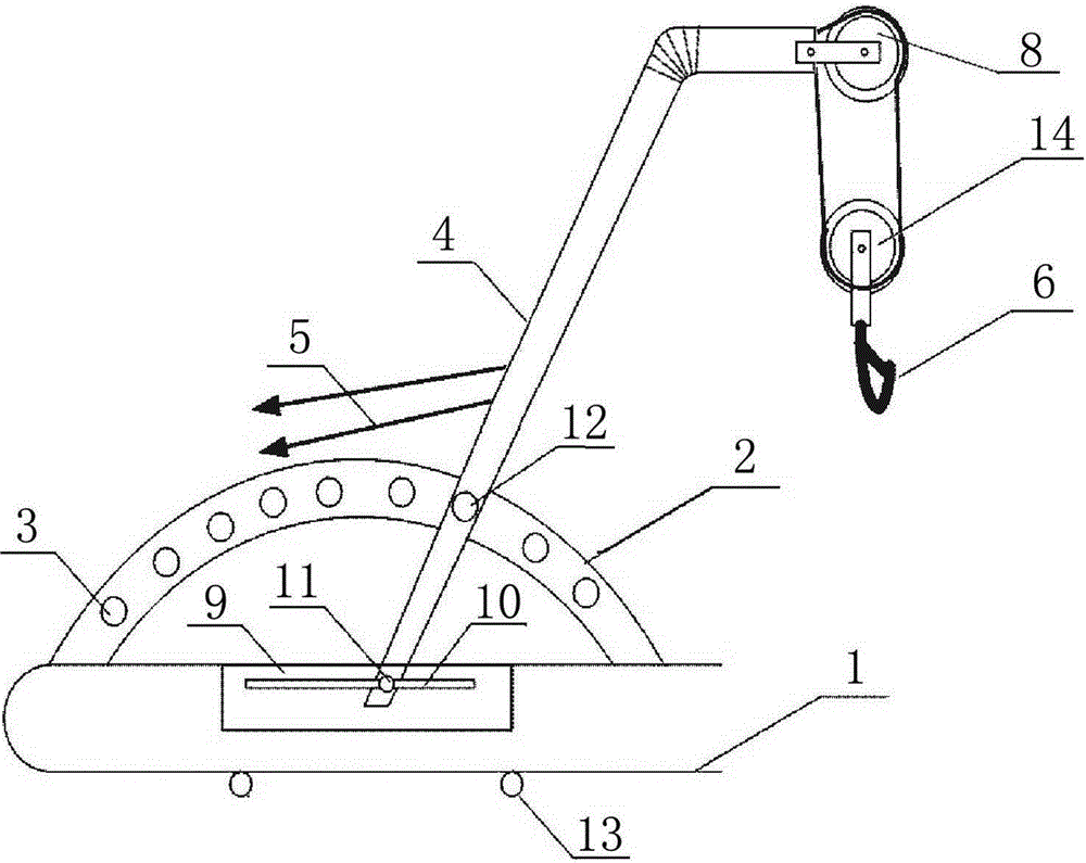
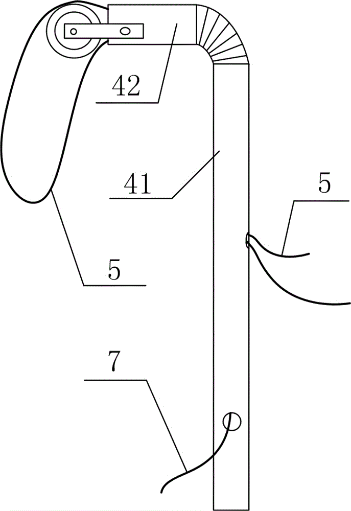
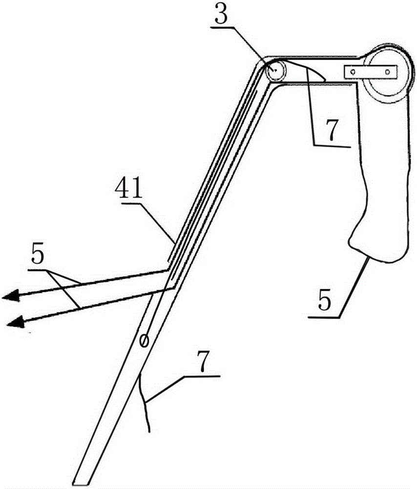
[0025] A labor-saving line lifter for mountains, such as Figure 1-Figure 3 As shown, it includes a U-shaped ring 1 for fixing to the cross arm of a utility pole, an adjusting hair plate 2 arranged on the U-shaped ring 1, an arc-shaped arrangement of adjusting holes 3 arranged on the adjusting ring 2, and one end The connecting rod 4 hinged on the U-shaped ring 1, the pulley block arranged on the connecting rod 4, the steel wire rope 5 arranged on the pulley block, the hook 6 suspended on one end of the steel wire rope 5, and the tight wire connected to the other end of the steel wire rope 5 The connecting rod 4 is composed of a main rod 41 whose one end is hinged on the U-shaped ring 1, and a mounting rod 42 whose one end is hinged on the other end of the main rod 41 and is used for the installation of the pulley block; the middle part of the adjustment hair plate 2 There is also a connecting rope 7 fixedly connected to it at one end, and the other end of the connecting rope ...

Embodiment 2

[0028] The difference between this embodiment and Embodiment 1 is that this embodiment optimizes the structure of the pulley block. In this embodiment, the pulley block is composed of a movable pulley 14 and a fixed pulley 8, and the movable pulley 14 is suspended on one end of the wire rope 5 and used for The hook 6 is fixed; the fixed pulley 8 is fixedly installed on the installation rod 42 .

[0029] And the quantity of this fixed pulley 8 in the present embodiment is two, is respectively positioned at the two ends of mounting rod 42, and the fixed pulley 8 at the position adjacent to main rod 41 can also be used as the pulley that is convenient to connect rope 7 to move at the same time; A pulley on which the connecting rope 7 moves is mounted inside the mounting bar 42 adjacent to the fixed pulley 8 . In the present embodiment, the fixed pulley 8 adjacent to the position of the main rod 41 is used as a pulley to facilitate the movement of the connecting rope 7, as figur...

Embodiment 3

[0031] The difference between this embodiment and Embodiment 2 is that the connection mode between the main rod 41 and the U-shaped ring 1 is optimized in this embodiment, and the specific settings are as follows:

[0032] The main rod 41 is fixedly installed on the U-shaped ring 1 through the connecting plate 9, wherein the connecting plate 9 is provided with a transverse bar-shaped mounting hole 10, and the bottom of the main rod 41 is fixed on the bar through the first fixing bolt 11. On the shaped mounting hole 10, the rod body on the main rod 41 close to the adjusting dish 2 is fixed on the adjusting hole 3 by the third fixing bolt 12.

[0033] This embodiment also optimizes the connection relationship between the U-shaped ring 1 and the cross-arm of the utility pole at the same time. The U-shaped ring 1 described in this embodiment is fixed on the cross-arm of the utility pole by the second fixing bolt 13, as figure 1 shown.


PUM


Abstract

The invention discloses a mountainous region laborsaving line lifting device, solving the problem that a current mountainous region line lifting device is greatly laborious. The mountainous region laborsaving line lifting device comprises a U-shaped knob ring used for fixing to an electric pole cross-arm; an adjusting disc arranged on the U-shaped knob ring; regulation holes arranged on the adjusting disc in an arc shape; a connecting rod with one end hinged to the U-shaped knob ring; a pulley block arranged on the connecting rod; a steel wire rope arranged on the pulley block; a hook suspended to one end of the steel wire rope; and a tightener connected to the other end of the steel wire rope. The steel wire rope is composed of a main rod having one end hinged to the U-shaped knob ring, and an installation rod having one end hinged to the other end of the main rod, and used for pulley block installation; the central section of the adjusting disc is also provided with a connecting rope having one end fixedly connected to the adjusting disc; the other end of the connecting rope extends from the interior of the main rod, penetrates into the installation rod, and is fixed in the middle part of the installation rod. The mountainous region laborsaving line lifting device can save labor and time, and effectively improve operation efficiency.

Description

technical field [0001] The invention relates to a line lifter, in particular to a labor-saving line lifter for mountainous areas. Background technique [0002] At present, in areas dominated by mountainous areas, the distribution lines tend to have too large spans and large wire diameters due to narrow passages. And the linear rod of the line is the most rod type in the power distribution line. The distribution line is different from the straight tower hanging bottle used in the transmission line, but the porcelain rod is used for hanging, so due to the large diameter of the line wire , The distance is too large and the weight is heavy, which causes a lot of pressure on the porcelain rod of the straight rod and is easy to break in the finished porcelain rod. In addition, lightning strikes or external force can easily cause the porcelain rod to break, and the wires may fall off from time to time. [0003] In addition, when replacing or maintaining the wires in the line trans...

Claims


Application Information

Patent Timeline
IPC IPC(8): H02G1/02
Inventor 邱程周方
Owner PANZHIHUA POWER SUPPLY COMPANY STATE GRID SICHUAN ELECTRIC POWER
Why Eureka
Try Eureka