
Corner line laying pulley

A technology of pay-off pulley and corner, applied in cable laying equipment and other directions, can solve problems such as damage to the pulley bracket, unbalanced force, unsatisfactory effect, etc., and achieve the effect of increasing the contact area, not easy to decoupling, and avoiding cable decoupling

Inactive Publication Date: 2016-02-03
国网山东潍坊市寒亭区供电公司 +1
View PDF8 Cites 9 Cited by
  • Summary
  • Abstract
  • Description
  • Claims
  • Application Information

AI Technical Summary

Problems solved by technology

The effect of this method is not ideal. Due to the different supports on both sides of the corner, the force is unbalanced, and problems such as damage to the bracket of the tackle and decoupling are often encountered.

Method used


Image

  • Corner line laying pulley
  • Corner line laying pulley
  • Corner line laying pulley

Examples


Embodiment Construction

[0027] In order to make the object, technical solution and advantages of the present invention clearer, the present invention will be further described in detail below in conjunction with the accompanying drawings and embodiments. It should be understood that the specific embodiments described here are only used to explain the present invention, not to limit the present invention.

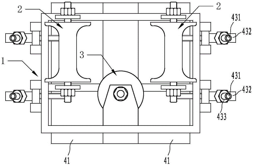
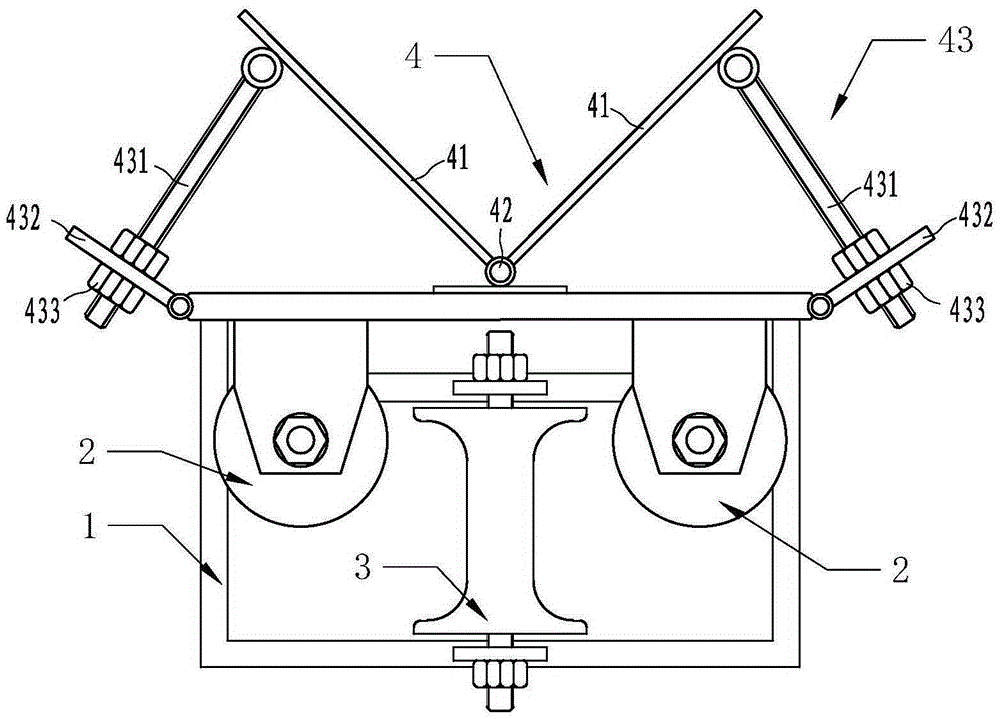
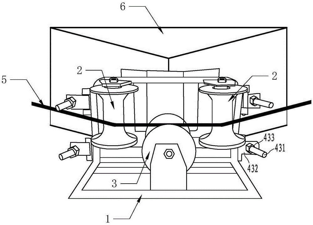
[0028] Such as figure 1 and figure 2 Commonly shown, the corner pay-off block includes a bracket 1, a guide pulley 2 and a support pulley 3 fixed on one side of the bracket 1 and arranged perpendicular to each other, and a fixing device 4 arranged on the other side of the bracket 1. Two guide pulleys 2 are provided, and the two guide pulleys 2 are arranged on both sides of the supporting pulley 3 respectively, and the supporting surface of the supporting pulley 3 is located between the two ends of the guiding pulley 2 . The guide pulley 2 and the support pulley 3 are all thin wire pulleys in the...


PUM


Abstract

The invention relates to the technical field of power installation equipment, and provides a corner line laying pulley. The corner line laying pulley comprises a support, a pulley fixed at one side of the support, and a fixation apparatus arranged at the other side of the support; the pulley comprises guiding pulleys and a supporting pulley which are arranged to be vertical to each other, and the two guiding pulleys are respectively arranged at the two sides of the supporting pulley; and the fixation apparatus comprises two fixation side plates hinged to each other. The corner line laying pulley is simple in structure and convenient to use, can fix the pulley at a corner of a building, enhances the contact area between the pulley and the building, protects the building from being damaged, effectively prevents a cable from unlocking and is higher in adaptability due to an adjustable included angle between the two fixation side plates.

Description

technical field [0001] The invention belongs to the technical field of electric installation equipment, and in particular relates to a corner pay-off pulley. Background technique [0002] The pay-off block is widely used in the electric power industry. It is used to extend and change the direction of cables when laying pipelines, to protect cables and reduce friction, reduce pipeline damage, and improve work efficiency. At present, in the process of unwinding power cables, the general terrain is complex, and it is often encountered that cables need to turn when passing through buildings and wells. The commonly used method is to place various corner blocks at the corners, but the existing blocks are often movable, and various types of supports need to be added during construction to fix the force on the cables, protect the blocks themselves from being pulled, and protect the cables from decoupling , to protect the building itself. The effect of this method is not ideal. Due...

Claims


Application Information

Patent Timeline
Patent Type & Authority Applications(China)
IPC IPC(8): H02G1/06
Inventor 孙全栋毕京雷赵飞杜阳马季忠徐雷明
Owner 国网山东潍坊市寒亭区供电公司
Learn More