Electric energy data acquisition local communication reliability test system and method
A technology for local communication and power consumption information, applied in transmission systems, digital transmission systems, electrical components, etc.
Inactive Publication Date: 2016-02-03
STATE GRID SICHUAN ELECTRIC POWER CORP ELECTRIC POWER RES INST +1
7 Cites 3 Cited by
AI-Extracted Technical Summary
Problems solved by technology
However, there is no more efficient and practical method in the prior art to test the communication capabilities of low-voltage power carrier communication...
Abstract
Provided are an electric energy data acquisition local communication reliability test system and method. The system comprises a host computer, a main communication unit and at least one slave communication unit. The host computer configures test parameters and source test data, controls the main communication unit and the slave communication unit to communicate in a local communication mode, and receives and analyzes target test data to obtain a communication state of a current channel; the main communication unit sends the source test data to the slave communication unit under the control of the host computer, and extracts communication parameters of the current channel to obtain the target test data; and the slave communication unit returns data to the main communication unit after receiving the source test data. The electric energy data acquisition local communication reliability test system and method can obtain a current communication performance of a communication module, and provide scientific basis for an electric energy data acquisition terminal to select a local communication mode.
Application Domain
Data switching networks
Technology Topic
Electric energyReal-time computing +5
Image
Examples
- Experimental program(1)
Example Embodiment
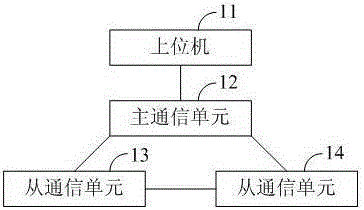
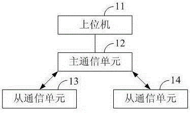
[0021] figure 1 It is a schematic structural diagram of a local communication reliability test system for electricity usage information collection according to an embodiment of the present invention. The electricity usage information collection local communication reliability test system includes a host computer 11, a master communication unit 12, and at least one slave communication unit. In this embodiment, the slave communication unit 13 and the slave communication unit 14 will be described as an example. It should be noted that when testing the reliability of the actual application of low-voltage power carrier communication in the field, the master communication unit 12, the slave communication unit 13, and the slave communication unit 14 adopt low-voltage power carrier communication modules; When the power wireless communication is reliable in actual field application, the master communication unit 12, the slave communication unit 13, and the slave communication unit 14 adopt micro-power wireless communication modules. The low-voltage power carrier communication module and the micro-power wireless communication module are both existing structures, and will not be repeated here.
[0022] Specifically, the host computer 11 is connected to the main communication unit 12, and is suitable for configuring test parameters and source test data, and controls the main communication unit 12, the slave communication unit 13, and the slave communication unit 14 to locally The communication mode is used to communicate, receiving and analyzing the target test data to obtain the communication status of the current channel. In this embodiment, the host computer 11 may be connected to the main communication unit 12 through a USB interface. Further, the host computer 11 includes a configuration module, a control module, and a processing module.
[0023] The configuration module is suitable for configuring test parameters and source test data according to the requirements input by the user. Through the visual input interface provided by the host computer 11, the user can set test parameters and source test data according to actual needs. The test parameters include local communication mode, message length, repeated data transmission times, data transmission path, and test times. In this embodiment, the maximum message length can be set to 250 Bytes, and the minimum can be set to 1 Byte. The data transmission path can be set from the master communication unit 12 directly to each slave communication unit, or it can be set as a slave communication unit. The master communication unit 12 passes through the middle slave communication unit to the next slave communication unit. The source test data may be directly input to the configuration module by the user, or may be randomly generated by the configuration module.
[0024] The control module is adapted to send the source test data to the master communication unit according to the configured test parameters, and wait to receive the response data from the slave communication unit forwarded by the master communication unit. After setting the test parameters and the source test data, the configuration module sends the source test data to the main communication unit 12 in the form of a message. The master communication unit 12 sends the source test data to the designated slave communication unit in the form of a message according to the configured local communication mode and data transmission path. After the designated slave communication unit receives the data sent by the master communication unit 12, it returns response data according to the original transmission path specified by the master communication unit 12, and the content of the response data is the instruction requested by the master communication unit 12 Make sure. The instruction requested by the main communication unit 12 can be set according to the actual needs of the user, which is not limited in this embodiment. During the data transmission process, the main communication unit 12 extracts the communication parameters of the current channel to obtain target test data, and feeds back the target test data to the host computer 11, and the target test data includes the From the response data of the communication unit, the communication parameters include signal quality and communication response time.
[0025] The processing module is adapted to analyze the target test data to obtain the communication status of the current channel, the communication status including the packet loss rate, signal strength, and communication conditions of different communication data loads. Further, the host computer 11 can provide the tester with the communication status of the current channel in an intuitive manner through a friendly visual interface.
[0026] Based on the above-mentioned electricity usage information collection local communication reliability test system, the embodiment of the present invention also provides a electricity usage information collection local communication reliability test method. figure 2. The method for testing the reliability of local communication for collecting electricity information includes:
[0027] Step S1: Install the master communication unit at the installation position of the electricity usage information collection terminal, and install the slave communication unit at the installation position of the smart meter. Further, when there are multiple slave communication units, the installation location of each slave communication unit is a randomly selected smart meter installation point.
[0028] Step S2, configure test parameters and source test data in the host computer. As mentioned above, through the visual input interface provided by the host computer 11, the user can set test parameters and source test data in advance according to actual needs. The test parameters include local communication mode, message length, number of repeated data transmissions, data Transmission path and number of tests.
[0029] Step S3: Input a test command in the upper computer, so that the upper computer controls the master communication unit to send the source test data to the slave communication unit to obtain the target test data in the current communication mode. After the communication channel is established, the host computer 11 sends the source test data to the main communication unit 12 in the form of a message, and the main communication unit 12 tests the source according to the configured local communication mode and data transmission path. The data is sent to the designated slave communication unit in the form of messages. After the designated slave communication unit receives the data sent by the master communication unit 12, it returns response data according to the original transmission path designated by the master communication unit 12. During the data transmission process, the main communication unit 12 extracts the communication parameters of the current channel to obtain the target test data, and feeds back the obtained target test data to the host computer 11, and the host computer 11 responds to the target test data. Perform analysis to obtain the packet loss rate, signal strength, and communication conditions of different communication data loads.
[0030] Taking testing the reliability of the actual application of low-voltage power carrier communication in the field as an example, the master communication unit 12, the slave communication unit 13, and the slave communication unit 14 are all low-voltage power carrier communication modules. During the test, first install the master communication unit 12 at the installation location of the electricity usage information collection terminal, and install the slave communication unit 13 and the slave communication unit 14 at randomly selected smart meter installation locations; Configure test parameters in the upper computer 11, and configure the local communication mode in the test parameters as low-voltage power carrier communication; input test commands in the upper computer 11, and the upper computer 11 controls the main communication unit 12 and specifies The low-voltage power carrier communication is performed between the slave communication units to obtain the packet loss rate, signal strength and communication conditions of different communication data loads in the low-voltage power carrier communication mode. Testing the reliability of micro-power wireless communication in the field is similar to testing the reliability of low-voltage power carrier communication in the field, so I will not repeat it here. When testing the reliability of RS485 bus communication in actual field applications, the RS485 bus can be directly used to connect the electricity consumption information collection terminal and the smart meter, and the upper computer 11 can control the electricity consumption information collection terminal and the smart meter to communicate. By comparing the reliability of various local communications in actual field applications, testers can optimize the communication scheme used in the field application environment according to the actual situation.
[0031] The power usage information collection local communication reliability test system and method provided by the present invention uses the master communication unit 12 to simulate an electricity usage information collection terminal, a slave communication unit to simulate a smart meter, and the host computer 11 to control the master communication The unit 12 communicates with each slave communication unit at the site of the electricity consumption information collection terminal in a local communication mode. Through the electricity consumption information collection local communication reliability test system and method provided by the present invention, the current communication performance, signal strength, interference strength, and communication stability of the communication module can be obtained in real time, thereby being able to test low-voltage power carrier communication and micropower The reliability and stability of the actual application of wireless communication in the field provide a scientific basis for the choice of local communication method for the electricity information collection terminal.
[0032] It should be noted that in the actual power user electricity consumption information collection system, there are usually multiple smart meters. Therefore, in the electricity consumption information collection local communication reliability test system provided in this embodiment, the main communication unit 12 There is more than one data transmission path to each slave communication unit. Hereinafter, the present invention will be further described in detail with reference to the embodiments and drawings, but the implementation of the present invention is not limited thereto.
[0033] Still taking the slave communication unit 13 and the slave communication unit 14 as an example, image 3 It is a schematic structural diagram of a local communication reliability test system for collecting electricity information according to an embodiment of the present invention. In this embodiment, the master communication unit 12 directly performs a first-level communication test on the slave communication unit 13 through a low-voltage power carrier or micro-power wireless, and directly performs a first-level communication test on the slave communication unit 14 through a low-voltage power carrier or micro-power wireless. Conduct level 1 communication test. The user can set the communication load size or select the default communication load size for testing. The upper computer 11 records the signal quality and communication response time of each communication for later data processing and query use.
[0034] Figure 4 It is a schematic structural diagram of a local communication reliability test system for collecting electricity information according to another embodiment of the present invention. In this embodiment, the master communication unit 12 directly performs a first-level communication test on the slave communication unit 13 through a low-voltage power carrier or micro-power wireless, and then performs a first-level communication test on the slave communication unit 14 through the slave communication unit 13 Secondary communication test. The user can set the communication load size or select the default communication load size for testing. The upper computer 11 records the signal quality and communication response time of each communication for later data processing and query use.
[0035] Figure 5 It is a schematic structural diagram of a local communication reliability test system for collecting electricity information according to another embodiment of the present invention. In this embodiment, the master communication unit 12 directly performs a first-level communication test on the slave communication unit 14 via low-voltage power carrier or micro-power wireless, and then performs the first-level communication test on the slave communication unit 13 via the slave communication unit 14 Secondary communication test. The user can set the communication load size or select the default communication load size for testing. The upper computer 11 records the signal quality and communication response time of each communication for later data processing and query use.
[0036] The above are only preferred embodiments of the present invention, and do not limit the present invention in any form. Any simple modifications or equivalent changes made to the above embodiments based on the technical essence of the present invention fall into the scope of the present invention. Within the scope of protection.
PUM


Description & Claims & Application Information
We can also present the details of the Description, Claims and Application information to help users get a comprehensive understanding of the technical details of the patent, such as background art, summary of invention, brief description of drawings, description of embodiments, and other original content. On the other hand, users can also determine the specific scope of protection of the technology through the list of claims; as well as understand the changes in the life cycle of the technology with the presentation of the patent timeline. Login to view more.