
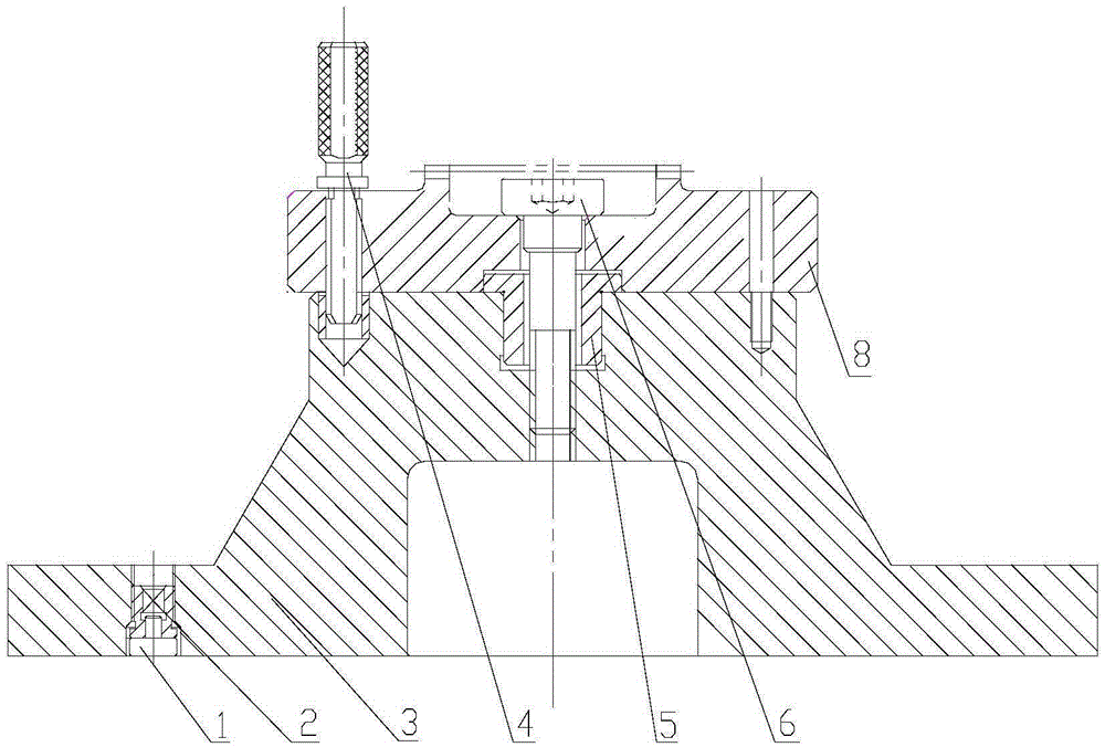
Arc end tooth grinding clamp

A technology of arc-end teeth and fixtures, which is applied to gear teeth, gear cutting machines, manufacturing tools, etc., and can solve problems such as high cost, complicated process, and difficult realization

Inactive Publication Date: 2016-02-10
HARBIN DONGAN ENGINE GRP
View PDF7 Cites 0 Cited by
  • Summary
  • Abstract
  • Description
  • Claims
  • Application Information

AI Technical Summary

Problems solved by technology

However, for some processing equipment with lower precision, it needs higher Precision fixtures, even sometimes difficult to achieve
At the same time, this self-centering fixture can only process a certain type of parts. When the parts are different, it is necessary to redesign and manufacture a set of special fixtures, which is complicated in process and high in cost.

Method used


Image

  • Arc end tooth grinding clamp

Examples


Embodiment Construction

[0007] As shown in the figure, the arc-end tooth grinding fixture includes a clamp body 3, a positioning sleeve 5, a compression screw 6, an orientation pin 4, and an adjustment screw 2. A hole is arranged at the center of the clamp body 3, and the hole The upper end is provided with a step, and the lower end is provided with a screw thread, and the lower part of the positioning sleeve 5 is fitted on the step at the upper end of the hole, and the upper part of the positioning sleeve 5 can be fitted on the notch of the part 8 to be processed; the compression screw 6 passes through After the center hole of the part 8 to be processed and the positioning sleeve 5, install it on the thread at the lower part of the center hole of the clamp body 3, and press the part 8 to be processed; Orientation holes are arranged at the positions of the parts to be processed, and the orientation pins 4 are respectively matched with the angular holes and the orientation holes after being inserted in...


PUM


Abstract

The invention relates to an arc end tooth grinding clamp which comprises a clamp body, a positioning sleeve, a pressing screw, a directional plug pin and an adjusting screw. The positioning sleeve is arranged in the center of the clamp body, and the upper portion of the positioning sleeve is installed on a spigot of a part to be machined in a matched mode. After the pressing screw penetrates through a center hole of the part to be machined and the positioning sleeve, the pressing screw is installed on a thread on the lower portion of a center hole of the clamp body. The clamp body is provided with a directional hole, and the directional plug pin is matched with an angular hole of the part to be machined and a directional hole. The adjusting screw is arranged on the lower portion of the clamp body. By means of the reasonable structure, the aim of machining high-precision arc end teeth in common machining equipment can be achieved. The clamp is reasonable in design and convenient to adjust. Different positioning sleeves are designed so that the aim of reducing cost can be achieved.

Description

technical field [0001] The invention relates to a grinding jig, in particular to a grinding jig for circular arc end teeth. Background technique [0002] In the mechanical rotor structure, the high-precision end face spline structure of circular arc end teeth is often used. This structure has the advantages of high meshing precision, good self-centering, and large transmission torque. The machining of the arc-shaped end teeth is through the positioning and clamping of the fixture, and the arc-shaped end teeth are directly ground and formed on the end face of the part by using a high-speed rotating cup-shaped grinding wheel. At present, the processing of high-precision arc-end teeth requires high-precision equipment, and it can only be realized with high-precision special fixtures. Special fixtures usually have automatic centering functions, such as expansion centering, taper fit centering, small gap fit centering, etc. However, for some low-precision processing equipment, ...

Claims


Application Information

Patent Timeline
Patent Type & Authority Applications(China)
IPC IPC(8): B23F23/06
Inventor 陈红霞林艳焱师玉英孙绪保吴泽刚满彦海王海军
Owner HARBIN DONGAN ENGINE GRP
Learn More