Bevel gauge for adjusting angle
An adjustable and protractor technology, applied in the field of measuring tools, can solve problems such as the inability to use horizontal and vertical methods, high precision requirements for sample production, waste of manpower and material resources, etc., and achieve the effect of simple structure, low cost and easy production
- Summary
- Abstract
- Description
- Claims
- Application Information
AI Technical Summary
Problems solved by technology
Method used
Image
Examples
Embodiment 1
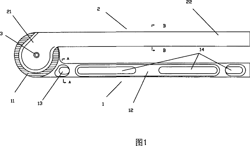
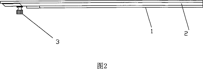
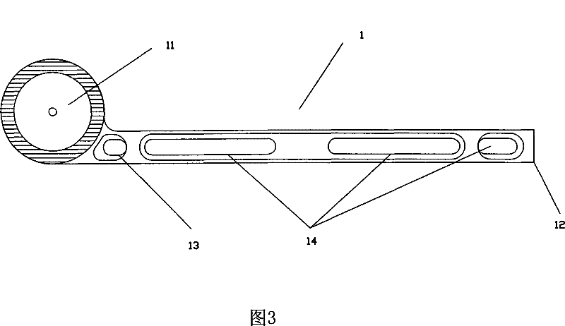
[0025] The angle-adjustable protractor in this embodiment consists of the first disc 11 on the first rotating arm 1, which is a stainless steel disc with a 360-degree scale engraved on its edge, which is divided into 360 equal parts, and each grid represents one degree. The first arm body 12 is made of I-shaped steel to ensure its strength. However, in order to reduce the inconvenience caused by the increase of the overall weight of the protractor by using the I-beam, two lightening holes 14 are specially provided in the groove of the I-beam to reduce its weight. The cross section is as follows Figure 4 shown. In addition, in order to keep the first rotating arm 1 in a horizontal state when used as a reference, a horizontal pipe 13 is embedded in the first arm body 12 . There is a blister in the horizontal tube 13. When the first arm body 12 is placed horizontally, the blister is in the middle of the horizontal tube 13. If it is not horizontal, it is at the edge. At this tim...
Embodiment 2
[0030] The structure of the protractor in this embodiment is basically the same as in Embodiment 1, the difference is:
[0031] A horizontal tube is also provided on the second arm body 2, so that the application range of the protractor can be expanded to meet the use requirements of different occasions. Both the first rotating arm 1 can be used as the horizontal reference to adjust the second rotating arm 2 to rotate at any angle, and the second rotating arm 2 can be used as the horizontal reference to adjust the first rotating arm 1 to rotate at any angle.
[0032] In this embodiment, the connecting head 21 on the second rotating arm 2 is designed as a second disc similar to the first disc 11 . But the radius of the second disc 24 is smaller than the radius of the first disc 11 , and the outer edge of the second disc is engraved with a scale similar to that of the first disc 11 . In this way, the scale plate on the first disc 11 and the scale plate on the second disc form t...
Embodiment 3
[0034] The structure in this embodiment is basically the same as in Embodiment 2, the difference is:
[0035]The second disk on the second rotating arm 2 has the same size as the first disk 11 on the first rotating arm 1, but it is made of transparent material, and the center of the circle of the second disk is the center to be provided with a cross line, the cross The four extension lines of the line are covered on the scale of the first disc 11, so that when the two discs overlap, they rotate relative to each other to control the angle more precisely.
PUM
 Abstract
Description
Claims
Application Information
 - R&D
- Intellectual Property
- Life Sciences
- Materials
- Tech Scout
- Unparalleled Data Quality
- Higher Quality Content
- 60% Fewer Hallucinations
Browse by: Latest US Patents, China's latest patents, Technical Efficacy Thesaurus, Application Domain, Technology Topic, Popular Technical Reports.
© 2025 PatSnap. All rights reserved.Legal|Privacy policy|Modern Slavery Act Transparency Statement|Sitemap|About US| Contact US: help@patsnap.com


