Automatic material tray lifting, clamping and translation mechanism

An automatic lifting and translation mechanism technology, which is applied in the direction of assembly machines, metal processing, metal processing equipment, etc., can solve the problems of low work efficiency, high labor intensity, time-consuming and laborious, etc., to reduce labor costs and operation intensity, and improve work efficiency Effect

Inactive Publication Date: 2016-02-10
JIANGSU JUSTECH PRECISION IND CO LTD
View PDF5 Cites 12 Cited by
  • Summary
  • Abstract
  • Description
  • Claims
  • Application Information

AI Technical Summary

Problems solved by technology

[0002] When assembling and processing electronic products, especially mobile phones, it is often necessary to place the parts in the tray jig, and then transport the tray to a specific processing position for processing and assembly. However, in the prior art, the tray is usually placed manually There are problems of high labor cost, low work efficiency, high labor intensity, time-consuming and labor-intensive problems when transporting to the designated processing location

Method used


Image

  • Automatic material tray lifting, clamping and translation mechanism
  • Automatic material tray lifting, clamping and translation mechanism

Examples


Embodiment Construction

[0033] Terms such as "upper", "lower", "left", "right", "front", "rear", and "middle" cited in the present invention are for the convenience of description, and figure 1 or figure 2 The views are drawn for reference, rather than limiting the scope of the present invention. Changes or adjustments of their relative relationships shall also be regarded as the scope of the present invention without substantive changes in the technical content.

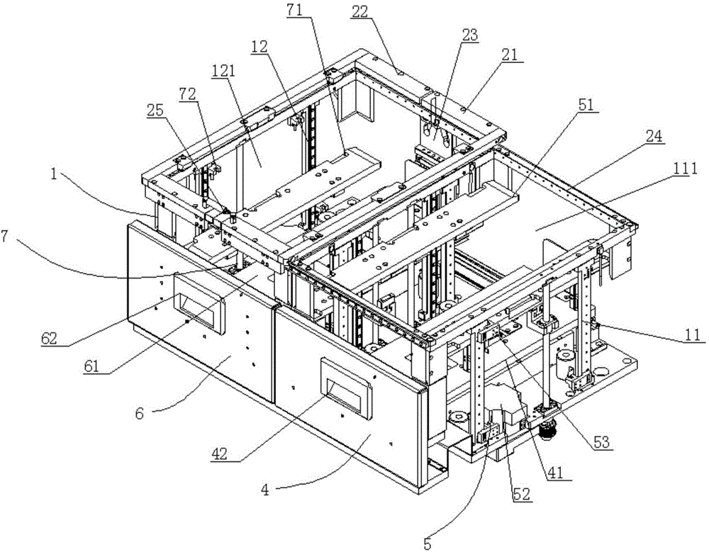
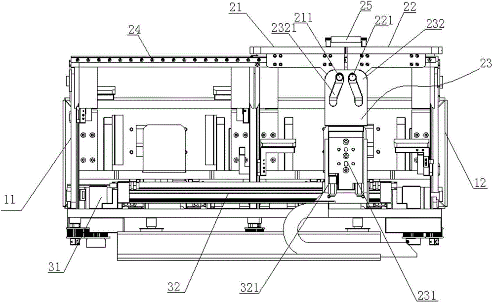
[0034] Such as figure 1 and figure 2 As shown, a tray automatic lifting and clamping translation mechanism includes a frame 1, a tray clamping device 2 and a tray translation device 3, and the frame includes a loading frame 11 and a blanking frame 12 arranged adjacently in sequence, The middle part of the feeding frame is formed with a feeding space 111, and the front side of the feeding frame is provided with a feeding drawer 4 for a drawer-type bearing tray, and the bottom of the loading frame is provided with a material tray for dri...


PUM


Abstract

The invention discloses an automatic material tray lifting, clamping and translation mechanism which comprises a frame, a material tray clamping device and a material tray translation device. The frame comprises a feeding frame and a discharging frame, wherein a feeding drawer for bearing a material tray in a drawer mode is arranged on the front side of the feeding frame, and a feeding, jacking and positioning device for driving the material tray to move vertically is arranged at the bottom of the feeding frame. A discharging drawer for bearing the material tray in a drawer mode is arranged on the front side of the discharging frame, and a discharging, jacking and positioning device for driving the material tray to move vertically is arranged at the bottom of the discharging frame. The material tray clamping device comprises a first clamping frame, a second clamping frame and a driving device, wherein the first clamping frame and the second clamping frame are positioned at the top of the frame in a sliding mode and are U-shaped, and the driving device drives the first clamping frame and the second clamping frame to be closed or opened. The material tray translation device can drive the material tray clamping device to perform left-right translation on the frame. The automatic material tray lifting, clamping and translation mechanism can achieve the functions of automatic lifting, clamping and positioning and translational conveying of the material tray and the like and accordingly achieves the purposes of improving the work efficiency and reducing the labor cost and operating strength.

Description

technical field [0001] The invention relates to an automatic feeding mechanism used in the field of assembly and processing of electronic products, in particular to an automatic lifting, clamping, and translation mechanism for a material tray. Background technique [0002] When assembling and processing electronic products, especially mobile phones, it is often necessary to place the parts in the tray jig, and then transport the tray to a specific processing position for processing and assembly. However, in the prior art, the tray is usually placed manually Transportation to the designated processing location has the problems of high labor cost, low work efficiency, high labor intensity, and time-consuming and labor-intensive problems. Contents of the invention [0003] In order to solve the above technical problems, the present invention proposes an automatic lifting, clamping and translation mechanism of the material tray, which can realize the functions of automatic lif...

Claims


Application Information

Patent Timeline
Patent Type & Authority Applications(China)
IPC IPC(8): B23P19/00B23P21/00
Inventor 景余祥
Owner JIANGSU JUSTECH PRECISION IND CO LTD
Why Eureka
Try Eureka