Printing system and method for printing substrates

A printing system, a technology for printing substrates, applied in printing, printing machines, printed circuits, etc., can solve the problems of limiting the utilization of the substrate surface, unable to set other components, unable to place orientation marks, etc., to achieve the effect of improving accuracy

Inactive Publication Date: 2016-02-10
EKRA AUTOMATISIERUNGSSYSTEME GMBH
View PDF8 Cites 4 Cited by
  • Summary
  • Abstract
  • Description
  • Claims
  • Application Information

AI Technical Summary

Problems solved by technology

However, the optical detection of one or more substrates has the disadvantage that optical alignment marks have to be applied separately to the substrate and possibly also to the printing template
However, in the case of transparent substrate surfaces, it is not always possible to place optically detectable orientation marks
By providing orientation marks on the substrate, it also results that other components (such as circuit components, etc.) cannot be placed in the area of ​​one or more orientation marks, which limits the utilization of the surface of the substrate when printing

Method used


Image

  • Printing system and method for printing substrates
  • Printing system and method for printing substrates
  • Printing system and method for printing substrates

Examples


Embodiment Construction

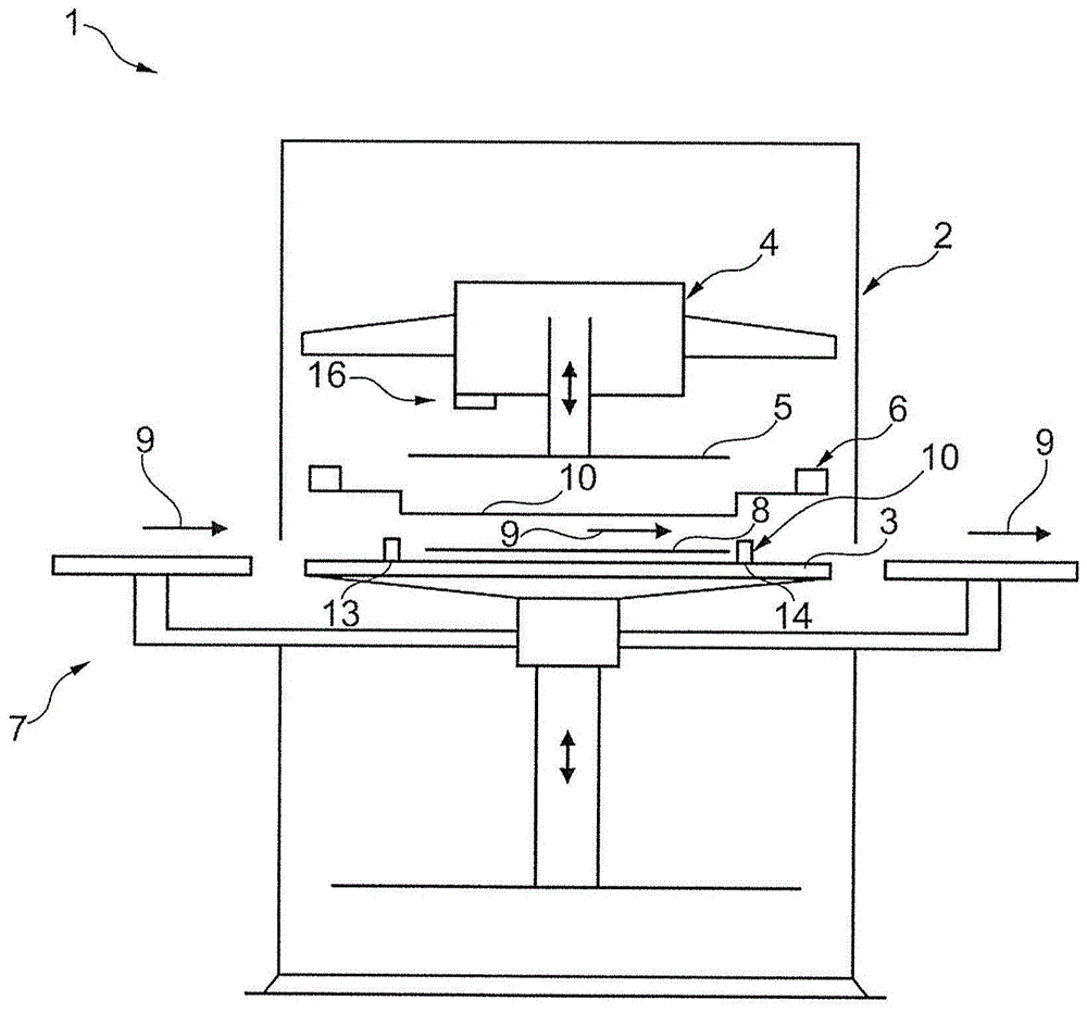
[0020] figure 1 A printing system 1 for printing substrates such as circuit boards, ceramic plates, solar cells, foils etc. is shown in a simplified illustration. The printing system 1 has a printing unit 2 with a printing table 3 and a squeegee arrangement 4 comprising at least one movable squeegee 5 . The printing table 3 and the squeegee 5 are designed in particular to be height-adjustable, as indicated by the double-headed arrow. Furthermore, the printing device 2 also has a printing template 6 arranged between the squeegee 5 and the printing table 3 .

[0021]Furthermore, a transport device 7 is also assigned to the printing unit, which is designed for this purpose to feed the substrate 8 shown here by way of example into the printing unit 2 , to transport it through the printing unit 2 between the stencil 6 and the printing table 3 . , and in turn output from the printing station 3 , as indicated by the arrow 9 indicating the transport direction of the substrate 8 or t...


PUM


Abstract

A printing system (1) for printing substrates (8), in particular printed circuit boards, includes a printing device (2) having at least one printing table (3) and a printing template (6) assigned to the printing table (3), and a means (10) for aligning the substrates on the printing table (3). The means further includes a first pair (11) of first slide elements (13, 14) and a second pair (12) of second slide elements (15, 16). The first pair of first slide elements can be displaced counter to one another along a first axis (22). The second pair of second slide elements can be displaced counter to one another along a second axis (23), which differs from the first axis (22). At least one drive device (19) is assigned to each pair (11, 12) for simultaneously displacing the slide elements (13-16).

Description

technical field [0001] The invention relates to a printing system for printing substrates (Substrates, substrates), in particular circuit boards, with a printing device comprising at least one printing station and a printing template assigned to the printing station, and for printing substrates on the printing station A facility for alignment (Ausrichten, calibration). [0002] Furthermore, the invention relates to a method for operating the printing system described above. Background technique [0003] As is often used in modern printing systems for processing circuit boards, ceramic plates, solar cells, foils, etc., the substrates are successively fed into the printing unit by input means and are aligned, printed, and The principles that are subsequently exported work. For alignment, it is known to provide cameras for optical inspection of the substrate and image analysis systems to be able to optimally align the substrate with the printing template based on one or more ...

Claims


Application Information

Patent Timeline
Patent Type & Authority Applications(China)
IPC IPC(8): B41F15/08B41F15/14B41M1/12B41M1/26
CPCH05K3/1233B41F15/0881B41F15/26B41F15/18B23Q1/262B23Q1/48H05K3/10H05K13/0015H05K2203/0165H05K2203/166
Inventor R·布罗西G·克劳斯K·曼格G·伊里巴谢
Owner EKRA AUTOMATISIERUNGSSYSTEME GMBH
Why Eureka
Try Eureka