Decelerating clutch casing of washing machine and washing machine

A deceleration clutch and washing machine technology, applied in the field of washing machines, can solve the problems of increasing the axial length of the deceleration clutch, and achieve the effects of increasing the washing capacity, reducing the overall height, and reducing the axial length

Active Publication Date: 2016-02-10
QINGDAO HAIER WASHING MASCH CO LTD
View PDF6 Cites 7 Cited by
  • Summary
  • Abstract
  • Description
  • Claims
  • Application Information

AI Technical Summary

Problems solved by technology

[0006] And existing deceleration clutch is all provided with shell, and the deceleration device of deceleration clutch is arranged in the shell, and clutch device is all arranged on the bottom of shell usually, like this, shell just only plays the effect of protecting deceleration device almost, and the setting of shell is invisible. Also increased the axial length of the reduction clutch

Method used


Image

  • Decelerating clutch casing of washing machine and washing machine
  • Decelerating clutch casing of washing machine and washing machine
  • Decelerating clutch casing of washing machine and washing machine

Examples


Embodiment approach

[0041] As a preferred embodiment of the present invention, it also includes a mounting plate 8, which is fixedly connected to the outer cylinder of the washing machine; the second end 193 is fixedly mounted on the mounting plate 8; the mounting plate 8 is provided with a tooth groove 9 for fixed engagement with the clutch sleeve 4 on one side facing the inner chamber.

[0042] The deceleration clutch housing of the present invention is made of metal material integrally formed, on the one hand, it can meet the stress requirements of the deceleration clutch housing, especially to meet the supporting effect of the bearing seat 195 of the first end 191 on the second bearing 14; on the other hand On the one hand, the processing is simple, and the installation and disassembly are convenient.

[0043] As a preferred embodiment of the present invention, the clutch device further includes an input shaft, a speed reduction device, an output shaft and an output bushing, the input end of ...

Embodiment 1

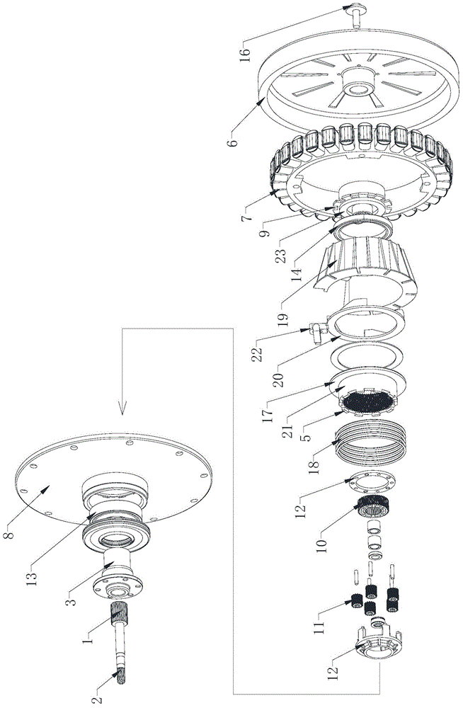
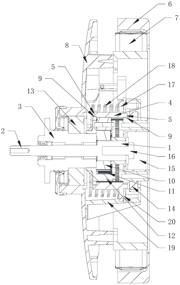
[0045] Such as figure 1 , figure 2 As shown, a washing machine deceleration clutch according to the present invention includes: an input shaft 1, a deceleration device, a clutch device, an output shaft 2 and an output sleeve 3, and the clutch device is arranged on the outer periphery of the deceleration device, on the line where the input shaft is located. The projections on are at least partially overlapped. The clutch device at least includes an axially movable clutch bushing, which is the inner ring gear of the reduction gear. The axial movement of the clutch bushing 21 is connected with structures in different states, and the control Different output states of the output shaft 2 and the output sleeve 3, the clutch sleeve 21 meshes with at least part of the gears in the reduction gear.

[0046] If the above-mentioned washing machine is a vertical bucket pulsator washing machine, the output shaft 2 is connected to the pulsator, and the output bushing 3 is connected to the ...

Embodiment 2

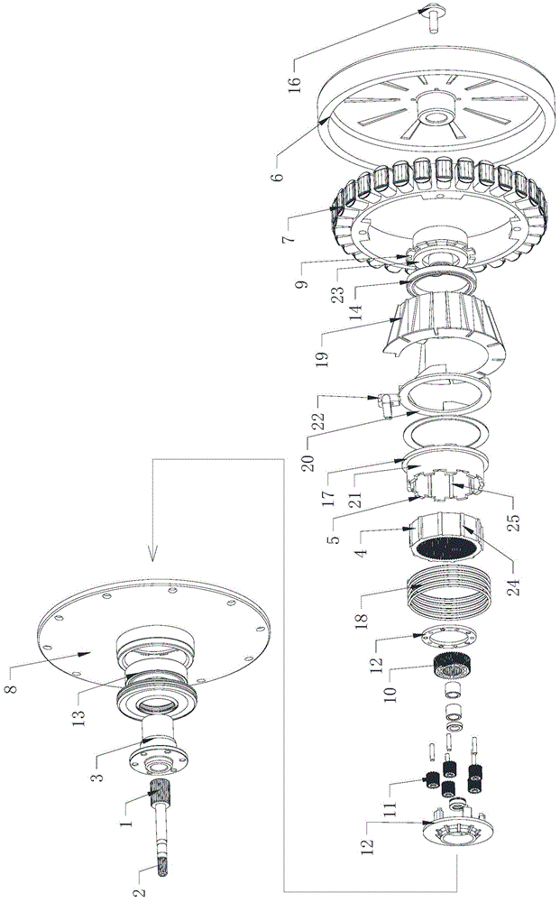
[0077] Such as image 3 , Figure 4 As shown, a washing machine deceleration clutch according to the present invention includes: an input shaft 1, a deceleration device, a clutch device, an output shaft 2 and an output shaft sleeve 3, the clutch device is arranged on the outer periphery of the deceleration device, and the clutch device is at least It includes a clutch sleeve 21 that can move axially. The clutch sleeve 21 is arranged outside the ring gear 4 of the deceleration device, and is connected with the ring gear 4 in an axially relatively sliding and circumferentially non-rotatable manner. 21 Axial movement connects the ring gear 4 to structures in different states through the clutch sleeve 21 to control the different output states of the output shaft 2 and the output sleeve 3, and the ring gear 4 meshes with at least part of the gears in the reduction gear .

[0078] If the above-mentioned washing machine is a vertical bucket pulsator washing machine, the output shaf...


PUM


Abstract

The invention provides a decelerating clutch casing of a washing machine. A decelerating clutch comprises a decelerating device and a clutch device; the decelerating clutch casing comprises an inner chamber, the decelerating device and at least parts of the clutch device are arranged in the inner chamber, and the clutch device arranged in the inner chamber comprises a clutch shaft sleeve and a clutch compression plate capable of driving the cultch shaft sleeve to move axially; the decelerating clutch casing cooperates with the clutch compression plate to enable the clutch compression plate to move axially; at least part of the decelerating clutch casing extends into an inner chamber of a stator of a direct driving motor. Structures of the decelerating device and the clutch device are mounted compactly, so that the overall height of the decelerating clutch casing is decreased, the overall height of the decelerating clutch is decreased, and the washing capacity of the washing machine with the same volume is increased.

Description

technical field [0001] The invention relates to the technical field of washing machines, in particular to a washing machine deceleration clutch shell and a washing machine. Background technique [0002] Washing machines are household appliances commonly used in people's daily life. According to different washing methods, they can be divided into drum washing machines and pulsator washing machines. A drum washing machine generally includes an outer tub, a drum and a motor, and the motor drives the drum to rotate in the outer tub to wash or dehydrate the clothes. Present drum washing machines simply utilize the rotation of the drum for washing, and only use the lifting ribs in the drum to lift and drop the laundry to beat the clothes for washing, so it is difficult to obtain excellent washing effect. The current drum washing machine also has a pulsator in the drum, and the pulsator and the drum are respectively driven by independent motors to optimize the washing effect. Due...

Claims


Application Information

Patent Timeline
Patent Type & Authority Applications(China)
IPC IPC(8): D06F37/30D06F37/40F16D48/00
Inventor 迟宗锐栾厚利李全德肖磊陈志李作强
Owner QINGDAO HAIER WASHING MASCH CO LTD
Why Eureka
Try Eureka