
Method for controlling concrete elevation by steel bar with hooked end

A technology of concrete and steel bars, applied in structural elements, building components, building reinforcements, etc., can solve the problem of non-slip surface of the upper steel bar, difficult to control the elevation, etc. Effect

Inactive Publication Date: 2016-02-10
ZHONGTIAN CONSTR GROUP
View PDF4 Cites 0 Cited by
  • Summary
  • Abstract
  • Description
  • Claims
  • Application Information

AI Technical Summary

Problems solved by technology

This approach solves the sinking problem of steel bars to a certain extent, but it is difficult to control the elevation when pouring concrete on the bottom slab, and it cannot solve the problem of anti-skid on the upper steel bar surface

Method used


Image

  • Method for controlling concrete elevation by steel bar with hooked end
  • Method for controlling concrete elevation by steel bar with hooked end

Examples


Embodiment Construction

[0016] The present invention will be further described below in conjunction with the accompanying drawings and specific embodiments.

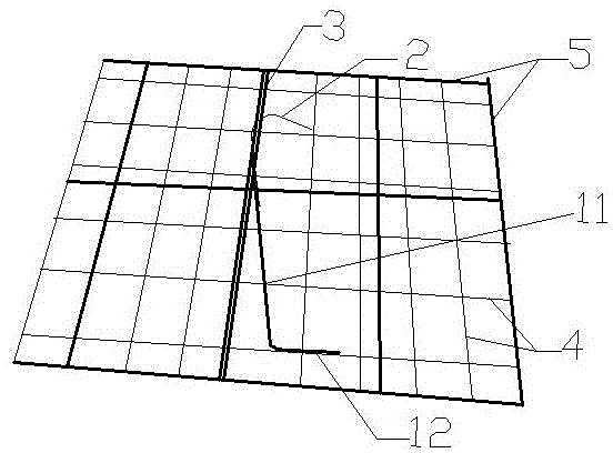
[0017] Such as Figures 1 to 2 As shown, it is an embodiment 1 of a method for controlling the level of concrete with a hook steel bar according to the present invention, including a steel bar bracket 1 and a steel bar hook 2, and the steel bar bracket 1 includes a steel bar bracket body 11 and a steel bar welded at the bottom end of the steel bar bracket 1 The diagonal brace 12, the steel bar support body 11 and the steel reinforcement diagonal brace 12 are steel bars of the same type, welded into an "L" shape.

[0018] In this implementation case, after the double-layer two-way steel bars of the bottom plate are bound, the diagonal bracing steel bars 12 of the "L" shaped steel bar bracket 1 are welded to the lower row of steel bars 4, the steel bar bracket body 11 is welded to the upper row of auxiliary steel bars 3, and the upper row The at...


PUM


Abstract

The invention discloses a method for controlling concrete elevation by a steel bar with a hooked end. The method comprises a steel bar support frame and a steel bar hook, wherein the steel bar support frame is welded into an L shape by two steel bars of the same specification; and the steel bar hook is bent to 135 degrees, and is welded with the steel bar support frame. The method comprises the following concrete implementation steps that 1, the two ends of the steel bar support frame are welded with an upper row auxiliary steel bar and a lower row steel bar and are separately arranged in the structure in a way of forming a distance being 1.5m; 2, the bottom end of the steel bar hook is welded with the steel bar support frame, and the length of a part, above the upper row auxiliary steel bar, of the bent end of the steel bar hook, is equal to the thickness of a protection layer; 3, concrete is cast; and 4, the bent end of the steel bar hook is used as an elevation control point of the concrete, and concrete leveling is performed. The method provided by the invention effectively solves the problem of upper part hogging bending steel bar subsidence due to manual treading or concrete casting in the construction process of a large-size concrete floor is effectively solved; the thickness of the steel bar protection layer is ensured; the floor surface elevation is effectively controlled; the manufacturing of components is simple; and the installation is simple.

Description

technical field [0001] The invention relates to a method for controlling the elevation of concrete with a hook steel bar. Background technique [0002] In the process of building construction, the elevation control of reinforced concrete structures often relies on 50 lines, and the upper row of steel bars often sinks due to trampling or concrete pouring. Reduced, greatly reducing the load-carrying capacity of the structure. In order to avoid this situation, measure steel bars are used in the current construction process, that is, common horse stool bars or steel brackets in engineering, which are arranged between the lower steel bar and the upper negative bending steel bar to support the negative moment bar. This approach solves the problem of steel bar sinking to a certain extent, but it is difficult to control the elevation when pouring concrete on the bottom slab, and it cannot solve the problem of anti-skid on the upper steel bar surface. Contents of the invention ...

Claims


Application Information

Patent Timeline
Patent Type & Authority Applications(China)
IPC IPC(8): E04C5/18
Inventor 楼亚东刘玉涛俞江峰徐双全肖婷
Owner ZHONGTIAN CONSTR GROUP
Learn More