

Multi-angle adjustable scaffold steel tube and steel tube scaffold
A kind of scaffolding and multi-angle technology, which is applied to the accessories of scaffolding, the connection of scaffolding, the support of building structures, etc. It can solve the problems of many connecting fastener parts, easy to lose parts loading and unloading, complex retractable structure, etc., and achieve overall stability Strong performance, improved utilization rate, flexible and convenient length adjustment
- Summary
- Abstract
- Description
- Claims
- Application Information
AI Technical Summary
Problems solved by technology
Method used
Image

Examples
Embodiment 1
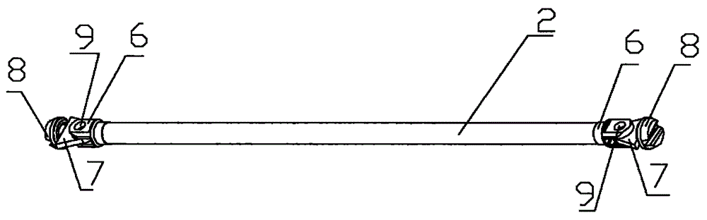
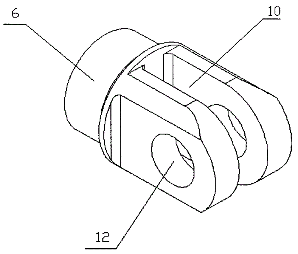
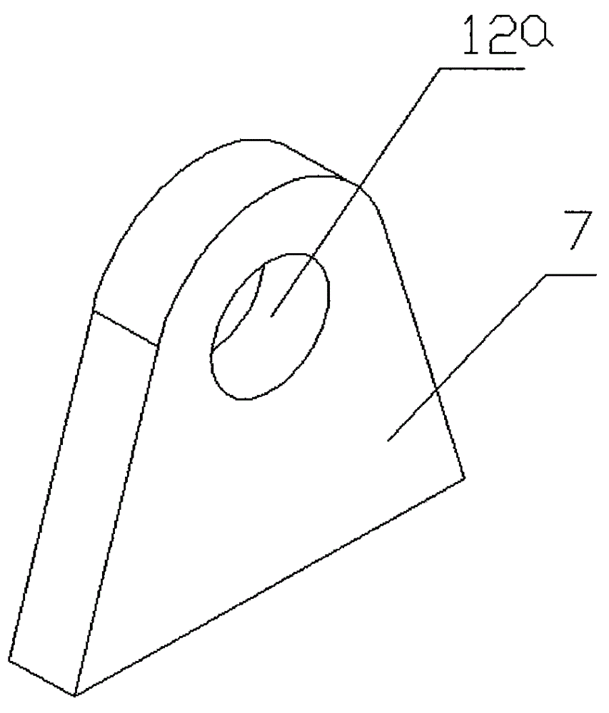
[0024] refer to Figure 1-Figure 4 As shown, the present invention provides a multi-angle adjustable scaffold steel pipe, the scaffold steel pipe is a horizontal bar 2 or a horizontal inclined bar 3, and also includes a lock head 6, a connecting piece 7, a socket base 8 and a connecting piece 9. The lock head 6 is flat and has a long slot 10 in the middle, through holes 12 are symmetrically opened on both sides of the lock head 6, and the lock head 6 is connected to the end of one side of the horizontal bar 2 or the horizontal slanting bar 3, and Its elongated slot 10 is far away from cross bar 2 or horizontal inclined bar 3 one side ends. One end of the connecting piece 7 is embedded in the long slot 10 of the lock head 6 and has a second through hole 12 a corresponding to the through hole 12 , and the other end of the connecting piece 7 is connected to the socket base 8 . The tail end of the socket base member 8 is connected to the connecting piece 7, and its head end inclu...
Embodiment 2
[0027] refer to Image 6As shown, the present invention provides another multi-angle adjustable scaffold steel pipe, that is, a lock head 6, a connecting piece 7, a fastener 13 and a connecting piece 9 are installed on the other side of the cross bar 2 or the horizontal slanting bar 3. The lock head 6 is flat and has a long groove 10 in the middle, through holes 12 are symmetrically opened on both sides of the lock head 6, and the lock head 6 is connected with the end of the other side of the cross bar 2 or the horizontal slant bar 3, And its long slot 10 is far away from the end of the other side of the cross bar 2 or the horizontal slanting bar 3 . One end of the connecting piece 7 is embedded in the long slot 10 of the lock head 6 and has a second through hole 12 a corresponding to the through hole 12 , and the other end of the connecting piece 7 is connected to the fastener 13 . The tail end of the fastener 13 is connected to the connecting piece 7, and its head end inclu...
Embodiment 3
[0029] refer to Figure 7 with Figure 8 As shown, in order to realize the length adjustability, the present invention changes the structure of the scaffold steel pipe. The cross bar 2 or the horizontal slanting bar 3 is set to include a fixed section 14 and screw rods 15 positioned on the left side / right side / left and right sides of the fixed section 14, the inside of the fixed section 14 is provided with internal threads, and the outside of the screw rod 15 is An external thread matching the internal thread of the fixing section 14 is provided, the head end of the screw rod 15 is threadedly connected with the fixing section 14 , and the end thereof is connected with the lock head 6 . When the lock head 6, the connecting piece 7, the socket base 8 or the fastener 13, and the connecting piece 9 are only installed on the left end or the right end of the cross bar 2 or the horizontal oblique bar 3, only install the wire on the left or right side of the fixed section 14. Rod 15...
PUM
 Abstract
Description
Claims
Application Information