Compressed air energy storage power generation method

A technology of compressed air energy storage and high-pressure air, which is applied in the field of electric power, can solve the problems of flame deflection, insufficient combustion of fuel and air, and low combustion efficiency, and achieve the effects of equipment simplification, suitable for popularization and use, and reduction of heat loss

Inactive Publication Date: 2017-11-28
CHINA DATANG CORP RENEWABLE POWER
View PDF7 Cites 0 Cited by
  • Summary
  • Abstract
  • Description
  • Claims
  • Application Information

AI Technical Summary

Problems solved by technology

[0005] However, how to fully mix the high-pressure air and gas, and then use the combustion equipment to fully burn and heat the two to maximize the heating efficiency has not been effectively resolved.
This makes it impossible to use compressed air for energy storage and power generation on a large scale.
[0006] At the same time, during the high-pressure air combustion process, the flame will deflect, resulting in insufficient combustion of fuel and air and low combustion efficiency.

Method used


Image

  • Compressed air energy storage power generation method
  • Compressed air energy storage power generation method
  • Compressed air energy storage power generation method

Examples


Embodiment 1

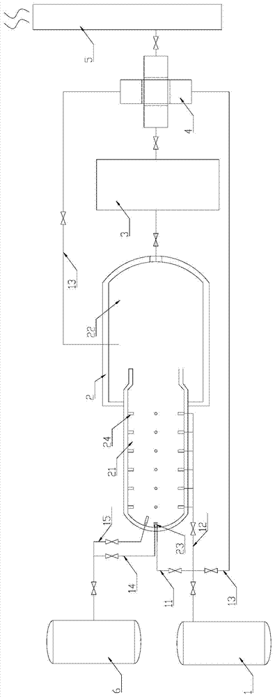
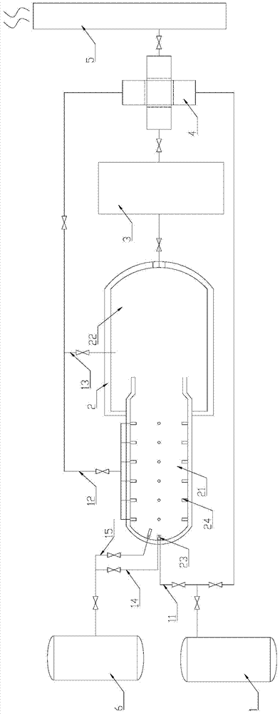
[0073] like figure 1 As shown, in this embodiment, the compressed air energy storage power generation system further includes an air preheater 4 . The air preheater 4 includes two independent passages capable of heat exchange, a first passage 41 and a second passage 42 . The two ends of the first passage 41 communicate with the air outlet of the storage tank 1 and the air inlet nozzle 23 of the air heater 2 respectively, so that the air heated by the air heater 2 flows through the first passage 41 first; The second channel 42 is connected with the exhaust port of the power generation equipment and the air inlet of the exhaust cylinder 5 respectively, so that the gas with a certain temperature after the power generation operation is completed flows in the second channel 42 . Since the first channel 41 and the second channel 42 are in contact, the gas in the first channel 41 and the second channel 42 can conduct heat exchange, so that the generated gas exchanges heat with the u...

Embodiment 2

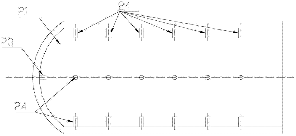
[0078] like Figure 9 to Figure 13 As shown, in this embodiment, the air preheater 4 includes a heat exchange structure 410 composed of a plurality of plates 40 stacked with a certain gap; the opposite sides of each plate 40 are bent upwards , cooperate with the upper plate 40 to form a channel for gas to flow through; the adjacent plates 40 are alternately arranged vertically and horizontally, forming a first channel 41 arranged horizontally and a second channel 42 arranged vertically.

[0079] like Figure 11 As shown, each plate 40 is a rectangular plate of the same shape; each plate 40 includes a pair of lateral sides 43 and a pair of vertical sides 44 respectively; the lateral sides 43 and vertical sides of adjacent plates 40 44 alternate upward bending. The upper end of the upwardly bent side of each plate 40 is respectively in contact with the bottom surface of the upper plate 40 and fixed by welding. The gap distance between adjacent boards 40 is not greater than 50...

Embodiment 3

[0089] like Figure 18 As shown, in this embodiment, the air preheater 4 includes two channels that are independent of each other and capable of heat exchange, and the two ends of the first channel 41 communicate with the air supply equipment and the air heater inlet respectively. ; Both ends of the second channel 42 are respectively connected with the solar collector 7 to form a circulation channel for the molten salt medium to flow.

[0090] The two ends of the second channel 42 communicate with the outlet of the solar heat collector 7 through the liquid inlet pipeline respectively, and communicate with the inlet of the solar heat collector 7 through the liquid outlet pipeline; The liquid pipelines are respectively provided with control valves for controlling the passages of the pipelines.

[0091] preferred, such as Figure 18 As shown, in this embodiment, a two-position three-way valve 9 is provided on the liquid inlet pipeline, and the three openings of the two-position...


PUM


Abstract

The invention relates to a compressed air energy-stored power generation method. The method comprises the step that high-pressure air and fuel are combusted and heated to generate high-temperature high-pressure mixed gas which is used for carrying out power generation. The combustion and heating process of the high-pressure air comprises the specific steps that S1, the first path of high-pressure air and the fuel are mixed and then are sprayed into a combustion chamber of an air heater from an air inlet nozzle so as to be combusted and heated; S2, the second path of high-pressure air is jetted into the combustion chamber along all the positions of the side wall of the combustion chamber of the air heater, and flames in the combustion chamber are jetted into a mixing chamber in the axis direction of the combustion chamber; and S3, the third path of high-pressure air and gas which is sprayed in after being heated by a self-heating combustion chamber are mixed in the mixing chamber, and the mixed gas with the pressure value being 2.0 Mpa and the temperature being 500-650 DEG C is generated and supplied to power generation equipment for power generation.

Description

technical field [0001] The invention relates to the field of electric power, in particular to a compressed air energy storage power generation system, and also to a compressed air energy storage power generation method. Background technique [0002] As the proportion of large-scale renewable energy such as wind power and solar photovoltaic in the grid is getting higher and higher, due to its volatility, many areas in our country have problems of abandoning wind, abandoning light and limiting electricity, which is not conducive to the development of renewable energy in our country , it is necessary to find a large-scale energy storage method suitable for water-scarce areas in northern my country. If the electric energy wasted in the phenomenon of abandoning wind and light is stored, and when the peak of electricity consumption arrives, this part of electric energy can be used to supplement the insufficient electricity, which can realize the function of peak shaving and valley ...

Claims


Application Information

Patent Timeline
Patent Type & Authority Patents(China)
IPC IPC(8): F02C3/34F02C6/16F02C7/08
CPCY02E60/16
Inventor 胡永生焦建清时文刚王赤夫王飞
Owner CHINA DATANG CORP RENEWABLE POWER
Why Eureka
Try Eureka