A method for forming a motor casing

A molding method and casing technology, applied in the field of motor parts, can solve problems such as affecting product performance, low work efficiency, complex process, etc., and achieve the effects of improving workpiece accuracy, reducing positioning work, and improving production efficiency

Active Publication Date: 2017-11-03
CHANGZHOU GONGLI SEIKI TECH
View PDF4 Cites 0 Cited by
  • Summary
  • Abstract
  • Description
  • Claims
  • Application Information

AI Technical Summary

Problems solved by technology

[0002] The casing of the existing motor is punched as a whole, and the punching of the side notch of the casing and the punching and bending of the pole claws are completed step by step through multiple molds. The precision of the motor casing is low, the process is complicated, and the work efficiency is low. Low, and the pole claws of the motor casing and the opening end of the side cutout are easily deformed, which affects product performance

Method used


Image

  • A method for forming a motor casing
  • A method for forming a motor casing
  • A method for forming a motor casing

Examples


Embodiment 1

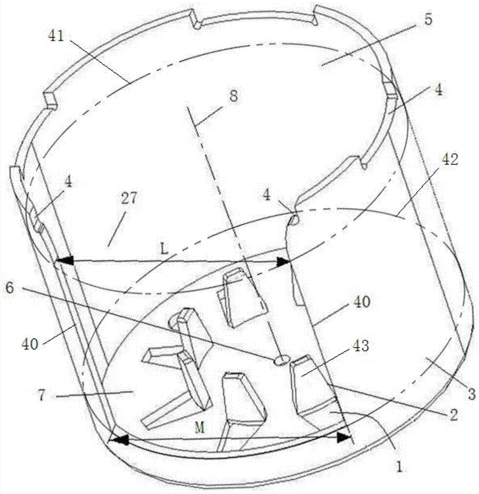
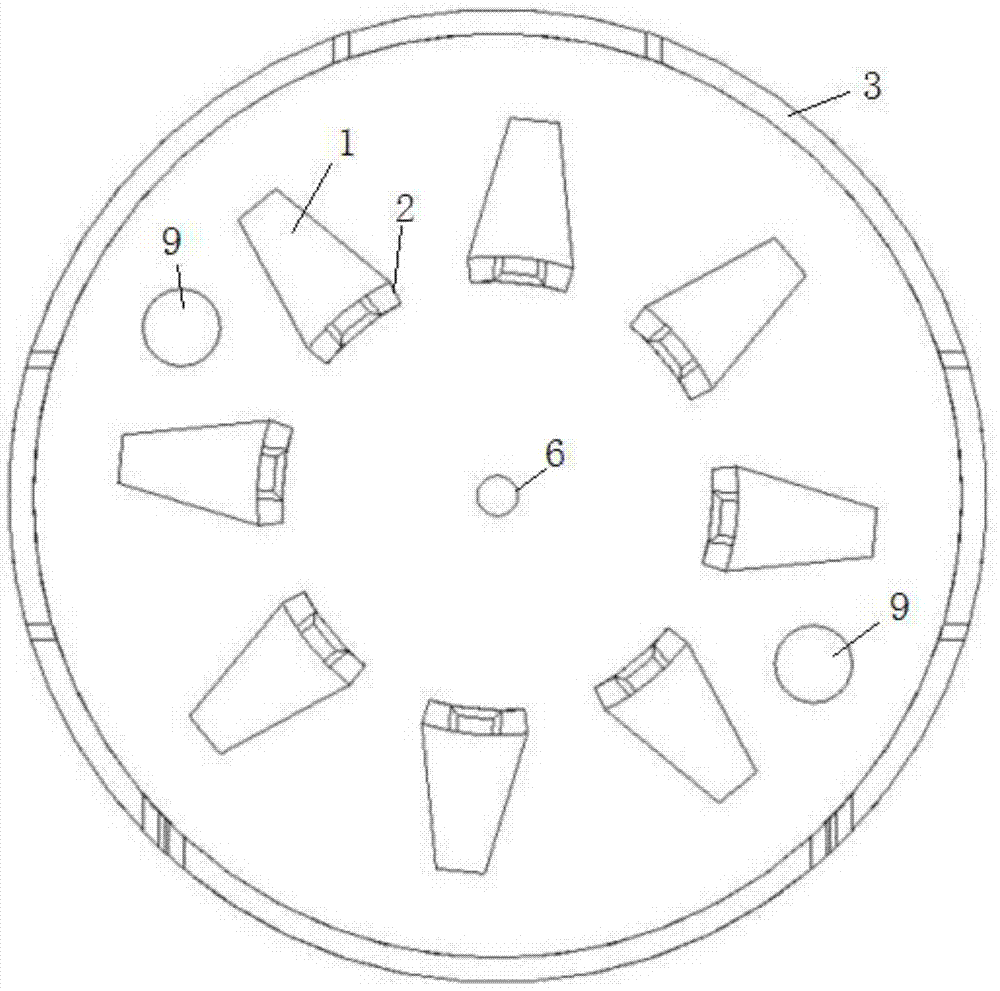
[0033] Depend on Figure 1-Figure 2 A motor casing shown includes a cylindrical shell surrounded by an annular side wall 3 and an end plate 7, the annular side wall 3 extends up and down, the end plate 7 is arranged at the bottom end of the annular side wall 3, and the shell The top end of the body is the opening end 5, that is, the top end of the annular side wall 3 is the opening end 5 of the housing, and the top surface of the annular side wall 3 is the top surface of the housing. The annular side wall 3 and the end plate 7 are of an integral structure.

[0034] The top of the annular side wall 3 is provided with a side cutout 27 and a cover plate installation groove 4 for installing the cover plate. The side cutout 27 and the cover plate installation groove 4 are radially transparent, and the notch of the cover plate installation groove 4 is upward. The side slit 27 extends downward from the top of the annular side wall 3 to the bottom of the annular side wall 3. The side...

Embodiment 2

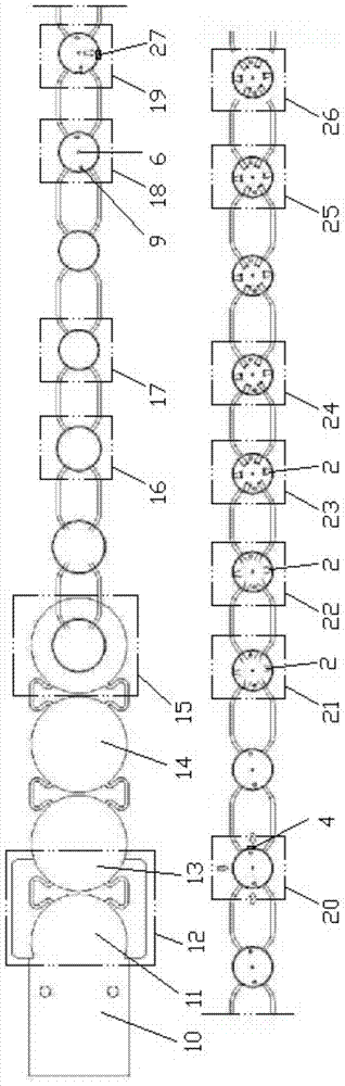
[0040] image 3 — Figure 11 It is a molding method of the motor casing described in Embodiment 1. The material strip 10 is walked in the continuous mold of the motor casing. Carry out the operation that comprises following operation to strip 10 on each station of continuous mould:

[0041] (1), the strip 10 cuts out the front side 13 with the front circular arc edge, the rear side 11 with the rear circular arc edge and the connecting belt on the first station 12, the rear side 11 and the rear side The material belt and the remaining material are thrown together as a whole, the front arc edge and the rear arc edge are set backwards, and when the front arc edge and the rear arc edge are connected, a full circle can be formed, and the connecting belt is connected between the front, Between the rear side parts 13 and 11, there are two connection belts connected between the adjacent front and rear side parts 13 and 11. The two connection belts are respectively located on the left ...


PUM


Abstract

The invention discloses a method for forming a motor casing. The material belt is walked in the continuous mold of the motor casing, and the operation of the material belt is carried out at each station of the continuous mold successively, including the following procedures: (1). Cut out the front side with the front arc edge, the back side with the rear arc edge and the connecting belt at the first station; (2) Draw the circular material sheet multiple times to form a ring side wall and end plate; (3), punching out the center hole and positioning hole for the end plate; (4), punching the side notch for the annular side wall, and the width of the upper opening of the side notch is smaller than the width of the lower end; (5), for The top side of the annular side wall punches the installation groove of the cover plate; (6), punches out the pole claw on the end plate; (7), performs arc-shaped bending on the pole claw; (8), punches the pole claw; (9) 1. Shaping the pole claws; (10) Rotary cutting the open end of the shell; (11) Cutting off the connecting belt. The invention relates to a continuous forming method of a motor case with pole claws and side cutouts that are not easily deformed and has high product performance.

Description

technical field [0001] The invention relates to parts of a motor, in particular to a motor casing and a forming method thereof. Background technique [0002] The casing of the existing motor is punched as a whole, and the punching of the side notch of the casing and the punching and bending of the pole claws are completed step by step through multiple molds. The precision of the motor casing is low, the process is complicated, and the work efficiency is low. Low, and the pole claws of the motor casing and the open end of the side cutout are easily deformed, which affects product performance. Contents of the invention [0003] The purpose of the present invention is to provide a continuous molding method of the motor casing with pole claws and side cutouts that are not easy to deform and have high product performance. [0004] In order to achieve the above object, the present invention adopts the following technical solutions: a motor casing molding method, the motor casin...

Claims


Application Information

Patent Timeline
Patent Type & Authority Patents(China)
IPC IPC(8): H02K5/04H02K15/14B21D53/00B21D35/00
Inventor 赵殿合黄文波谈国民
Owner CHANGZHOU GONGLI SEIKI TECH
Why Eureka
Try Eureka