Workbench with copper bar bending machine

A workbench and curved row technology, applied to workbenches, manufacturing tools, etc., can solve the problems of decreased work efficiency of workers, disruption of on-site work order, and easy separation of products, so as to ensure work order, reduce fatigue, and ensure work efficiency Effect

Inactive Publication Date: 2016-02-17
SUZHOU SUZHU IND CONTROL ENG TECH RES CENT CO LTD
View PDF7 Cites 0 Cited by
  • Summary
  • Abstract
  • Description
  • Claims
  • Application Information

AI Technical Summary

Problems solved by technology

[0002] The bending machine workbench is a workbench for placing the bending machine to bend the copper bars. The existing bending machines are placed directly on the ground, requiring workers to squat down for operation. For long-term bending and squatting operations, workers It is prone to fatigue, which leads to a decrease in the work efficiency of workers, and the existing workbench is only a supporting plane. During the bending process of the bending machine, the product is easy to break away from the entire workbench, thereby destroying the work order on site

Method used


Image

  • Workbench with copper bar bending machine

Examples


Embodiment Construction

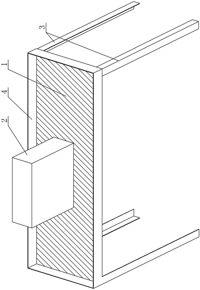
[0012] A bending machine table, see figure 1 : It includes a table top 1 and a bending machine 2, the bottom of the bending machine 2 is supported on the upper surface of the table 1, the table 1 is supported on the upper parallel support point formed by a combination of several columns 3, and the outer periphery of the table 1 is raised to form a guardrail 4.

[0013] Specifically, there are four columns 3, the table top 1 is a rectangular table top, and a column 3 is respectively arranged at the four corners of the table top 1, and the lower end surfaces of the four corners of the table top 1 are respectively supported on the upper ends of the column 3 at the corresponding position;

[0014] The column 3 is specifically an angle iron, and its cross section is an L-shaped structure, and the upper end of each column 3 is respectively welded to the corresponding position of the lower end of the table top 1;

[0015] The height dimension of the guardrail 4 is greater than the d...


PUM


Abstract

The invention provides a workbench with a copper bar bending machine. The work state that workers bend down to work for a long time is effectively avoided, the fatigue of the workers is relieved, the work efficiency of the workers is ensured, products cannot be disengaged from a whole workbench table board, and the work order on the site is ensured. The workbench with the copper bar bending machine comprises the table board and the copper bar bending machine, wherein the bottom of the copper bar bending machine is supported on the upper end face of the table board. The workbench is characterized in that the table board is supported on upper end parallel supporting points formed by combining multiple stand columns; the periphery of the table board upwards protrudes to form a guardrail.

Description

technical field [0001] The invention relates to the technical field of workbench structures, in particular to a workbench for a row bending machine. Background technique [0002] The bending machine workbench is a workbench for placing the bending machine to bend the copper bars. The existing bending machines are placed directly on the ground, requiring workers to squat down for operation. For long-term bending and squatting operations, workers It is easy to cause fatigue, which leads to a decrease in the work efficiency of workers, and the existing workbench is only a supporting plane. During the bending process of the bending machine, the product is easy to break away from the entire workbench, thereby destroying the work order on site. Contents of the invention [0003] In view of the above problems, the present invention provides a bending machine workbench, which effectively solves the working state of the workers bending over for a long time, reduces the fatigue of t...

Claims


Application Information

Patent Timeline
Patent Type & Authority Applications(China)
IPC IPC(8): B25H1/02B25H1/20B21D5/00
CPCB25H1/02B21D5/00B25H1/20
Inventor 余自
Owner SUZHOU SUZHU IND CONTROL ENG TECH RES CENT CO LTD
Why Eureka
Try Eureka