Fixing structure

Inactive Publication Date: 2006-03-16
YAZAKI CORP
View PDF0 Cites 22 Cited by
  • Summary
  • Abstract
  • Description
  • Claims
  • Application Information

AI Technical Summary

Benefits of technology

[0028] As described above, when a bolt (or bolt thread) is inserted into the bolt insertion hole, the fixing part can be provisionally fixed to the bolt thread, w

Problems solved by technology

Due to this, since the fastening work has to done by the one hand, the work becomes difficult to be done and needs to take a long time.
Thus, a plurality of pieces of work such as holding work and fastening work of the fixed member need to performed at the same time, and this constitutes one of causes of the reduction in working efficiency.
On top of this, there is a possibili

Method used


Image

  • Fixing structure
  • Fixing structure
  • Fixing structure

Examples


first embodiment

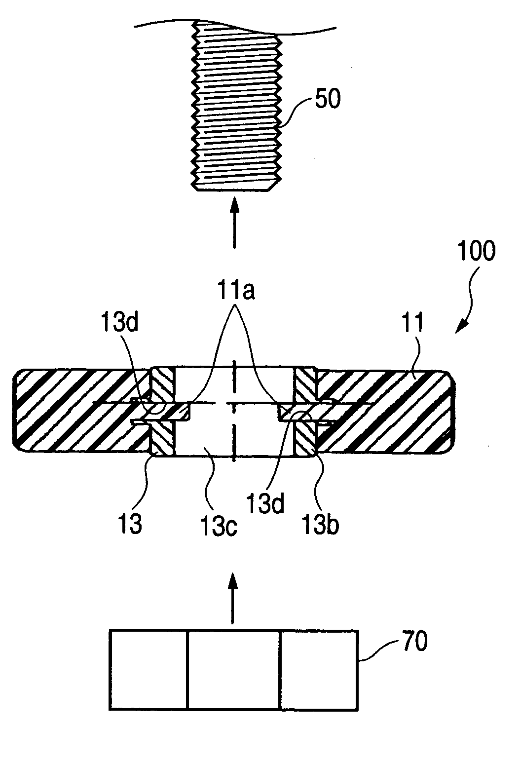
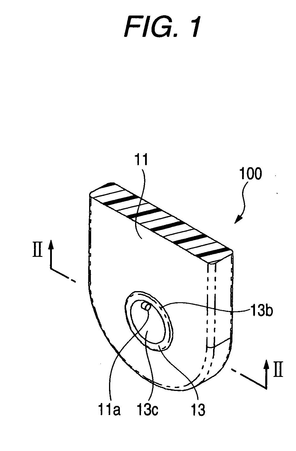
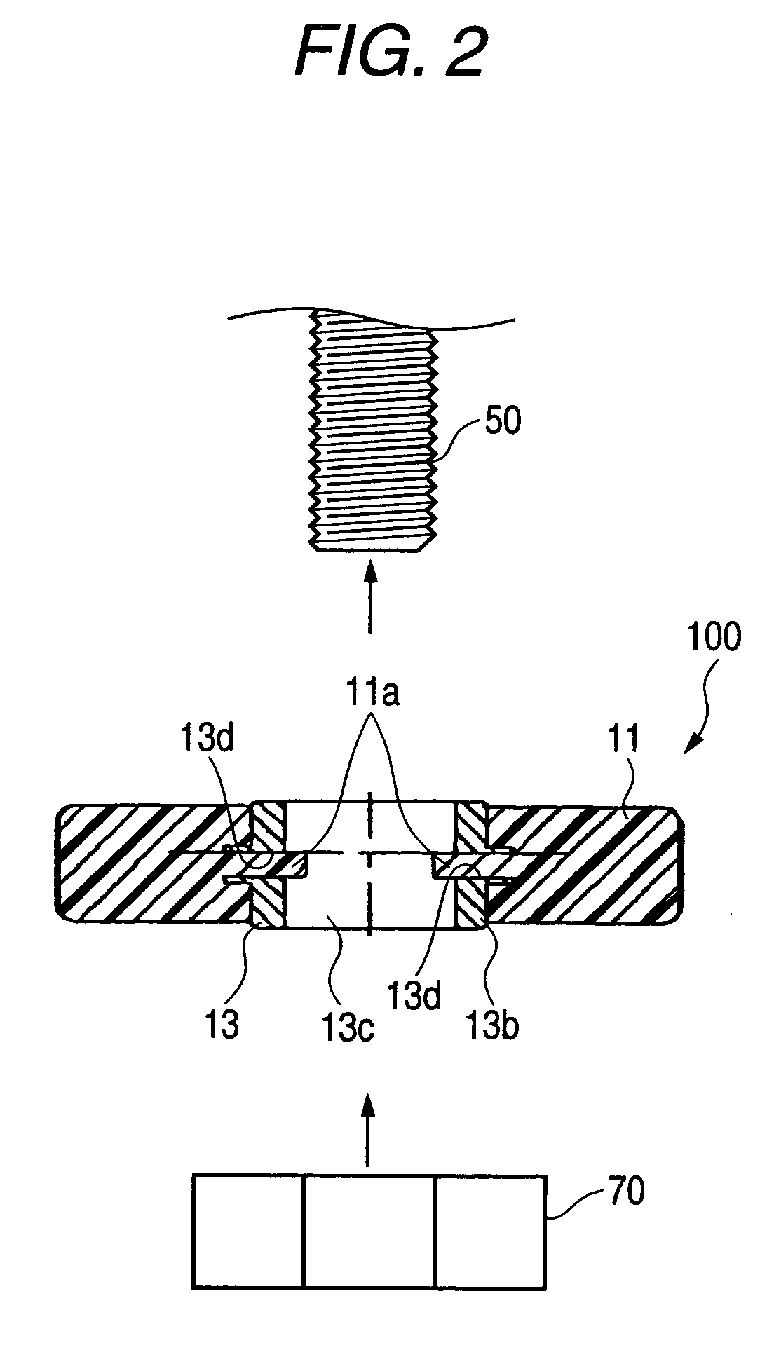
[0046]FIG. 1 is a perspective view of a fixing structure which is a first embodiment of the invention, FIG. 2 is a cross-sectional view of the fixing member taken along the line II-II in FIG. 1 as viewed in a direction indicated by arrows at ends of the line, and FIG. 3 is a perspective view of a collar in FIG. 1.

[0047] As shown in FIGS. 1 to 3, a fixing structure 100 is an attachment tab that is formed integrally on a fixed member (whose a main body is not shown) such as a junction block, a relay block, a protector, a bracket and the like. To be more specific, the fixing structure 100 includes a synthetic resin fixing part 11 that is formed on the fixed member (whose main body is not shown), a metallic collar 13 which is fixed to the fixing part 11 and which has a bolt insertion hole 13c, and two engaging protrusions 11a, 11a which are formed integrally with the fixing part 11 so as to protrude into the bolt insertion hole 13c of the collar 13. Then, a bolt thread 50 such as a bol...

second embodiment

[0051] Next, a second embodiment will be described with reference to FIGS. 4 to 6. FIG. 4 is a perspective view of a fixing structure which is a second embodiment of the invention, FIG. 5 is a cross-sectional view of the fixing member taken along the line V-V in FIG. 4 as viewed in a direction indicated by arrows at ends of the line, and FIG. 6 is a perspective view of a collar shown in FIG. 4.

[0052] As shown in FIGS. 4 to 6, a fixing structure 200 is an attachment tab that is formed integrally on a fixed member (whose a main body is not shown) such as a junction block, a relay block, a protector, a bracket and the like. To be more specific, the fixing structure 200 includes a synthetic resin portion 21 to be fixed that is formed on the fixed member (whose main body is not shown), a metallic collar 23 which is fixed to the portion 21 to be fixed and which has a bolt insertion hole 23c, and two engaging protrusions 21a, 21a which are formed integrally with the portion 21 to be fixed...

third embodiment

[0057] Next, a third embodiment will be described with reference to FIGS. 7 to 9. FIG. 7 is a perspective view of a fixing structure which is a third embodiment of the invention, FIG. 8 is a cross-sectional view of the fixing member taken along the line VIII-VIII in FIG. 8 as viewed in a direction indicated by arrows at ends of the line, and FIG. 9 is a perspective view of a collar shown in FIG. 7.

[0058] As shown in FIGS. 7 to 9, a fixing structure 300 is a fixing part 31 which is something like a rectangular plate-like convex portion and which is formed at part of a fixed member. A collar 33 fits in the fixing part 31, and a crimp portion (not shown) is formed at a peripheral end portion of the collar 33 that is crimp machined so that the collar 33 is fixed to the fixing part 31. In the metallic collar 33, a bolt insertion hole 33c that is defined in a flat circular shape by a flat circular edge portion 33a penetrates therethrough in an axial direction of the collar 33, and a flan...


PUM


Abstract

A fixing structure includes a synthetic resin fixing part that is formed on a fixed member, a metallic collar adapted to be fixed in the portion to be fixed and having a bolt insertion hole and two engaging protrusions which are formed integrally with the fixing part so as to protrude into an interior of the bolt insertion hole. Then, when a bolt is inserted into the bolt insertion hole, the inserted bolt is then engaged with the engaging protrusions, whereby the fixed member is provisionally fixed to the bolt. In this state, a nut is fittingly screwed on a distal end portion of the bolt which protrudes from the bolt insertion hole.

Description

BACKGROUND OF THE INVENTION [0001] 1. Field of the Invention [0002] The present invention relates to an improved fixing structure into which a bolt thread of a bolt is inserted. [0003] 2. Related Art [0004] A wiring harness related synthetic resin fixed member such as a junction block, a relay block, a protector, a bracket and the like which are attached to a vehicle such as an automobile is fixed to a vehicle body with a bolt thread of a bolt. As shown in FIGS. 13 to 15, a portion 1 to be fixed to the vehicle has a synthetic resin attachment tab 2, which constitutes a fixing part, and a metallic collar 3. The attachment tab 2 is provided at a predetermined location of the fixed member, and the collar 3 is attached to the attachment tab 2. To be more specific, the collar 3 fits in a through hole 2a which is formed in the attachment tab 2 and is defined by a circular edge portion of the tab. The collar 3 is something like a hollow cylindrical member formed of a metal in order to sati...

Claims


Application Information

Patent Timeline
IPC IPC(8): F16B39/00
CPCF16B43/00F16B41/002
Inventor ISHIMARU, TSUTOMUHONMA, MICHIAKI
Owner YAZAKI CORP
Why Eureka
Try Eureka