
Emergency safety device for car tire explosion

A safety device and tire blowout technology, applied in vehicle parts, tire parts, transportation and packaging, etc., can solve problems such as vehicle steering system and braking system out of control, vehicle skidding, major traffic accidents, etc., to ensure controllability and convenience Effect of replacement and maintenance

Inactive Publication Date: 2016-02-17
林春
View PDF6 Cites 8 Cited by
  • Summary
  • Abstract
  • Description
  • Claims
  • Application Information

AI Technical Summary

Problems solved by technology

The rim directly touches the ground, because the friction coefficient of the rubber tire and the metal rim on the ground is very different, causing the steering system and braking system of the vehicle to lose control; the vehicle will skid severely and appear sideslips and rollovers, which can easily lead to major traffic ACCIDENT

Method used


Image

  • Emergency safety device for car tire explosion
  • Emergency safety device for car tire explosion
  • Emergency safety device for car tire explosion

Examples


Embodiment 1

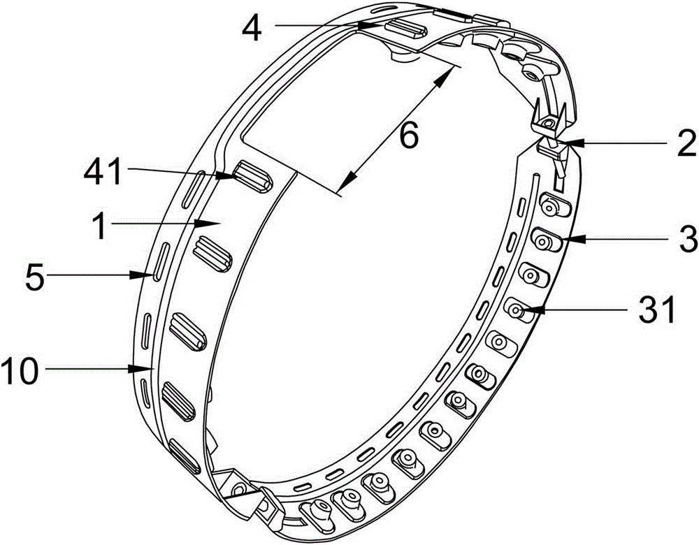
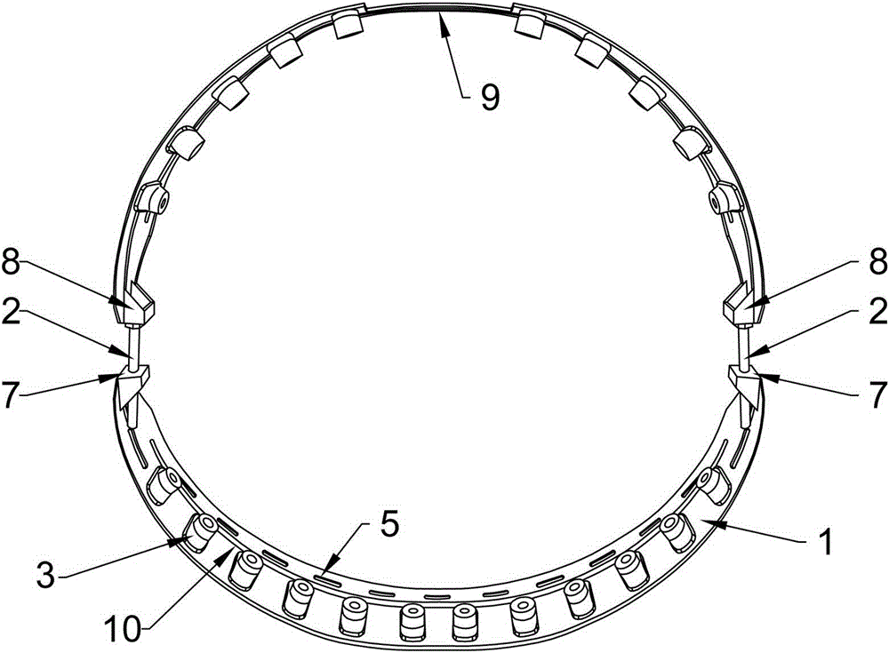
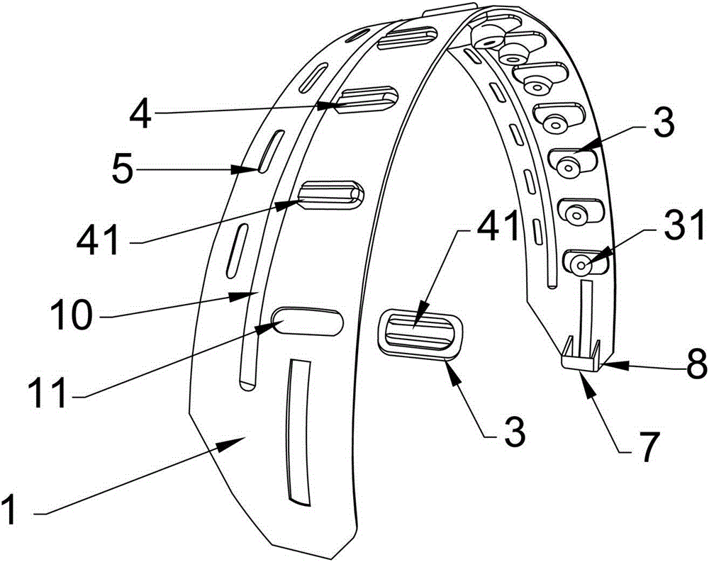
[0036] This embodiment provides an emergency safety device for automobile tire blowout, such as Figures 1 to 3 As shown, the safety device of this embodiment includes a ring composed of two annular support belts 1. The support belt 1 is made of high-strength rigid material, which has high strength and is not easily deformed, and plays a supporting role in the car when the car is blown out or running out of air. . Adjacent ends of two adjacent annular support belts 1 are connected by adjustable fasteners 2 .

[0037]Each support belt 1 is provided with a number of evenly distributed installation grooves 11 , the centers of each installation groove 11 are located on the same circumference of the lower half of the support belt 1 , and are used to install the support block 3 and the toothed engagement bar 4 . The support block 3 is arranged on the radially inner surface of the support belt 1 , and the toothed bite strips 4 and the bite teeth 41 are arranged on the radially outer...

Embodiment 2

[0047] like image 3 As shown, this embodiment is different from Embodiment 1 in that, in actual use, some vehicles are not equipped with a tire pressure monitoring device (TPMS). None of the tire pressure monitoring "concave" mounting positions 6 for the pressure monitoring device (TPMS) need to be provided.

Embodiment 3

[0049] like Figure 10 As shown, this embodiment differs from Embodiment 1 in that the widths of the wheel grooves 12 on the wheel rims 13 of different vehicles are different, so the width of the supporting belt 1 to be installed also changes with the change of the wheel grooves 12 . When the wheel groove 12 is narrow, the support belt 1 is correspondingly narrowed, so that the counterweight balance hole 5 and the "concave"-shaped installation position 6 cannot be opened on the support belt 1; therefore, the installation groove 11 in the length direction of the support belt 1 Position, a reinforcing rib 10 structure is provided on the left and right, which can also achieve the effect of strengthening the structure and the balance of the counterweight.


PUM


Abstract

The invention discloses an emergency safety device for car tire explosion. The safety device comprises a circular ring composed of at least two annular support bands, the adjacent ends of every two adjacent annular support bands are connected through an adjustable fastening part, and the annular support bands are installed in wheel grooves of wheel rims to be used; the radial inner surface of each support band is provided with a plurality of support cushion blocks which are evenly distributed, the inner end surface of each support cushion block is in a regular shape, and horizontal surfaces or oblique surfaces with the 10-degree oblique angles serve as the inner end surfaces; the radial outer surface of each support band is provided with a plurality of tooth-shaped engaging strips, the outer surfaces of the tooth-shaped engaging strips are provided with engaging teeth, and when the emergency safety device is used, the tooth-shaped engaging strips are closely engaged with the inner wall of a tire. According to the emergency safety device for car tire explosion, the structure is reasonable, assembling and disassembling are convenient, the tire and the wheel rims can keep synchronous running in the states of tire explosion or tire gas deficiency, the controllability of a steering and braking system is guaranteed, traffic accidents are reduced, and the traffic safety is improved.

Description

technical field [0001] The invention provides a safety device in the field of automobiles, and in particular relates to an emergency safety device for vehicles using vacuum tires when the tires of the vehicle are blown or the tire pressure is lower than the standard tire pressure. Background technique [0002] Today's vehicles basically use vacuum tires, so it is necessary to open a wheel groove with a certain width and depth on the rim of the vehicle. When installing and removing the tire, the bead of the tire is pressed into the groove, so that the bead The rim can be turned over the rim for easy tire installation and removal. [0003] In actual use, when the vehicle is moving, the tire suddenly blows out or the tire is out of air (the tire pressure is lower than the standard tire pressure), if the tire is flat or the degree of air loss is serious, the bead will slide into the wheel groove , the tire will separate from the rim. The rim directly touches the ground, becaus...

Claims


Application Information

Patent Timeline
Patent Type & Authority Applications(China)
IPC IPC(8): B60C17/04
CPCB60C17/04
Inventor 林春
Owner 林春
Learn More