Parking locking mechanism for automobile speed changer

A technology of automobile transmission and locking mechanism, applied in mechanical equipment, components with teeth, transmission control and other directions, can solve the problems of gear impact, labor, and easy damage of gearbox, and achieve long service life and large contact area. , the effect of high braking torque

Active Publication Date: 2016-02-17
黄山市开发投资集团有限公司
View PDF12 Cites 12 Cited by
  • Summary
  • Abstract
  • Description
  • Claims
  • Application Information

AI Technical Summary

Problems solved by technology

[0003] A good parking lock mechanism is an important means to ensure reliable parking of the car. Judging from the current domestic situation, in fuel vehicles equipped with automatic transmissions, there are generally special parking mechanisms inside the transmission, usually It is realized by the parking pawl and the parking ratchet. When parking, when the gear is pushed into the P position, the parking pawl is pressed down, the parking pawl and the parking ratchet are engaged, and the drive wheel of the gearbox is locked; but if If the driver does not pay attention, when parking the car, he directly shifts to the P gear. Once the car is parked with a slight slope, the parking pawl and the parking ratchet will always be under stress; When pulling to other gears, it will be very difficult, and it will cause a huge impact on the gear at the moment of disengagement. If this is done for a long time, the gearbox will be easily damaged; at the same time, because the parking mechanism relies on the parking pawl and the parking ratchet to However, it is impossible for the pawl and the ratchet to engage well in any position, so cars using automatic transmissions often have a slight slippage when parking

Method used


Image

  • Parking locking mechanism for automobile speed changer
  • Parking locking mechanism for automobile speed changer
  • Parking locking mechanism for automobile speed changer

Examples


Embodiment Construction

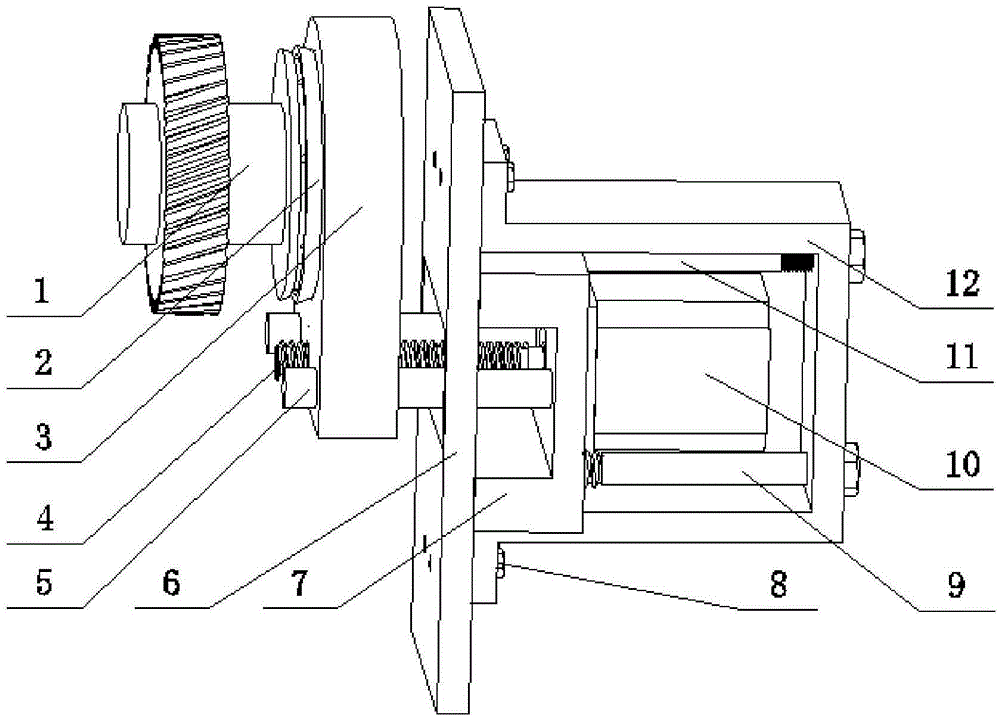
[0022] In this embodiment, the parking lock mechanism for the automobile transmission is composed of a locking mechanism part and a manual unlocking mechanism part.

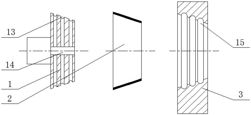
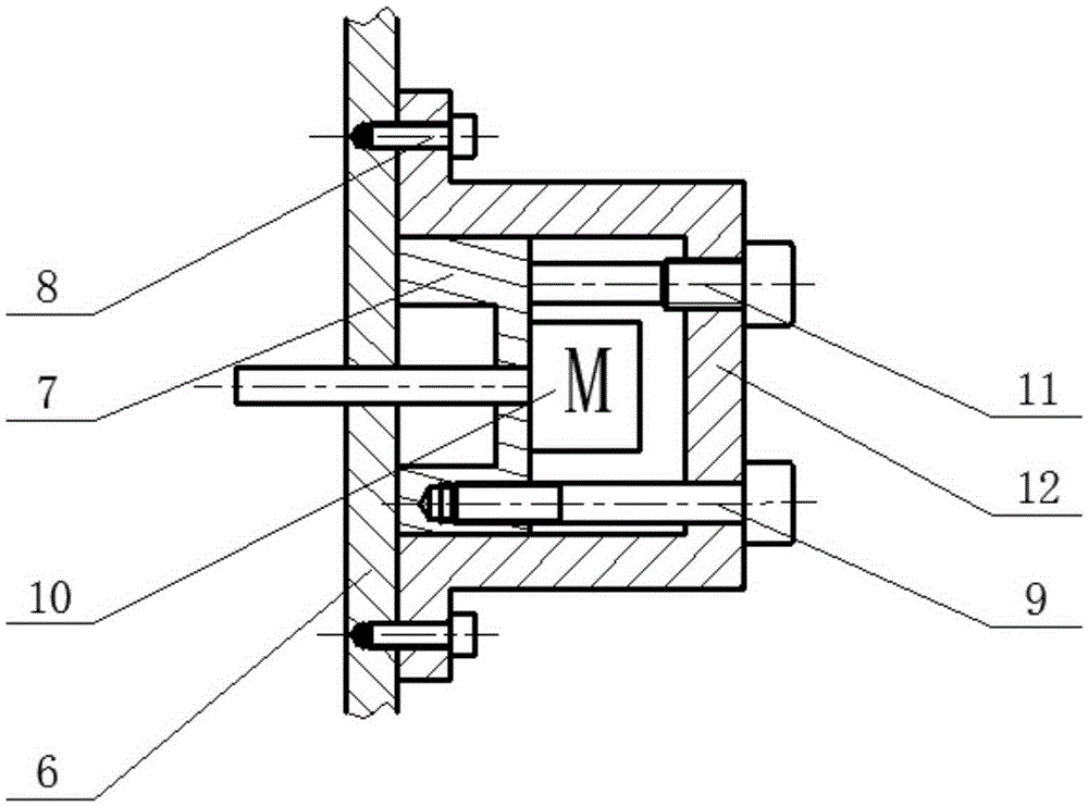
[0023] see figure 1 , figure 2 and Figure 4 , the locking mechanism part is made up of a tapered surface intermediate shaft 1, a friction ring 2, a tapered surface locking ring 3, a lead screw 4, a guide rod 5 and a motor 10; the tapered surface intermediate shaft 1 is installed in the gearbox, and The output shaft of the box is fixedly connected, the shaft end is in the shape of a conical surface, and the outer periphery contains several rows of oil unloading grooves 13; the oil unloading grooves (13) are connected with the through hole 14 of the shaft center, which can remove the Lubricating oil; the friction ring 2 is conical in shape and can be made of oil-resistant materials, high wear-resistant metal powder and other raw materials, and is in movable contact with the tapered intermediate shaft 1 and the ...


PUM


Abstract

The invention discloses a parking locking mechanism for an automobile speed changer. The parking locking mechanism for the automobile speed changer is characterized in that the parking locking mechanism comprises a locking mechanism body and a manual unlocking mechanism; the locking mechanism body is composed of a conical surface intermediate shaft, a friction ring, a conical surface locking ring, a lead screw, a guide rod and a motor; the shaft end of the conical surface intermediate shaft is in a conical surface shape, and the periphery of the conical surface intermediate shaft comprises multiple rows of oil discharge grooves which are connected with a through hole in the shaft center; an inner hole of the conical surface locking ring is conical and comprises multiple oil return grooves; the motor is controlled to rotate to drive the conical surface locking ring, the friction ring and the conical surface intermediate shaft for combination so as to achieve braking of the speed changer; the concentricity of three conical surfaces of the conical surface intermediate shaft, the friction ring and the conical surface locking ring can be guaranteed during mounting of the parking locking mechanism, so that braking accuracy is guaranteed and automobile sliding is avoided. Power-off self-locking and power-on unlocking are achieved; the control operation is simple; the structure is compact; comprehensive functions are achieved; the reliability and the stability of parking braking are effectively improved.

Description

technical field [0001] The invention relates to a parking lock mechanism suitable for an automobile transmission. Background technique [0002] The advent of automatic transmissions has reduced the driver's sense of tension when driving a car and improved driving comfort. At present, the research on automatic transmission mainly focuses on the promotion of transmission gears, which have been developed into 4th gear, 6th gear, 8th gear and 9th gear, and even higher. But at the same time, good parking functions are gradually being paid attention to. [0003] A good parking lock mechanism is an important means to ensure reliable parking of the car. Judging from the current domestic situation, in fuel vehicles equipped with automatic transmissions, there are generally special parking mechanisms inside the transmission, usually It is realized by the parking pawl and the parking ratchet. When parking, when the gear is pushed into the P position, the parking pawl is pressed down,...

Claims


Application Information

Patent Timeline
Patent Type & Authority Applications(China)
IPC IPC(8): F16H63/34
CPCF16H63/3416F16H63/3433F16H63/345F16H63/3466F16H63/3491
Inventor 陈奇徐帆樊浩高峰张振
Owner 黄山市开发投资集团有限公司
Why Eureka
Try Eureka