
Trip mechanism and earth leakage protector

A technology for a tripping mechanism and a switching mechanism, applied in the field of tripping mechanisms, can solve the problems of reduced flexibility of the tripping mechanism, rising costs, and difficulty in adjusting the magnetic field distribution of moving elements, so as to improve reliability and sensitivity, and reduce magnetic resistance. , design and manufacture flexible and efficient effects

Active Publication Date: 2017-12-01
SCHNEIDER ELECTRIC IND SAS
View PDF7 Cites 0 Cited by
  • Summary
  • Abstract
  • Description
  • Claims
  • Application Information

AI Technical Summary

Problems solved by technology

However, in the above-mentioned tripping mechanism of the prior art, due to the use of an annular permanent magnet, it is difficult to adjust the magnetic field distribution relative to the moving element, so it is necessary to design different permanent magnets and different installations for tripping mechanisms with different sensitivity requirements. structure
This reduces flexibility and increases costs in manufacturing trip mechanisms with different sensitivities

Method used


Image

  • Trip mechanism and earth leakage protector
  • Trip mechanism and earth leakage protector
  • Trip mechanism and earth leakage protector

Examples


Embodiment Construction

[0031] Various embodiments of the present disclosure will now be described in detail, by way of example only.

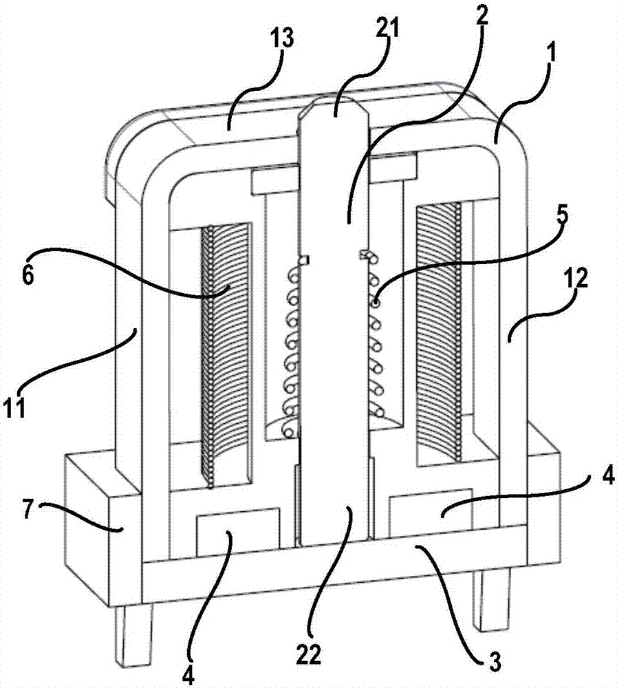
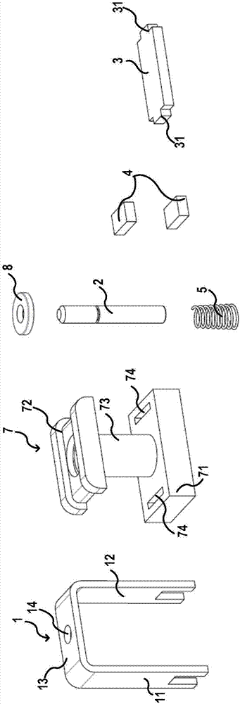
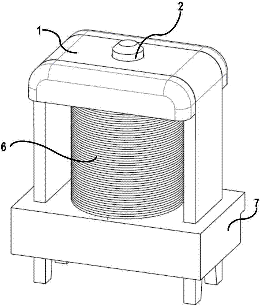
[0032] refer to Figure 1-3 , which shows a trip mechanism according to one embodiment of the present disclosure. The tripping mechanism includes: a magnetically permeable frame 1 having two legs 11 , 12 and a middle portion 13 connecting the two legs 11 , 12 , preferably forming a U-shaped magnetically permeable frame 1 . A pin hole 14 is provided on the middle part 13 of the magnetically permeable frame 1 . The frame 1 can be easily formed by bending a strip of material.

[0033] The tripping mechanism also includes a coil support 7 , and the coil support 7 includes a base 71 , a frame support part 72 and a coil support part 73 connecting the base 71 and the frame support part 72 . The middle part 13 of the magnetically permeable frame 1 is supported by the frame support portion 72 , and the ends of the two legs 11 , 12 of the magnetically permeable frame 1 are ...


PUM


Abstract

A tripping mechanism, comprising a magnetic conductive frame (1) which is provided with two support legs (11, 12) and an intermediate part (13) connecting the two support legs (11, 12); a pin (2) capable of being axially and movably arranged between the two support legs (11, 12); a magnetic conductive plate (3) coupled to free ends of the two support legs (11, 12); a bias mechanism (5) for providing an acting force for the pin (2); and a coil (6) which surrounds the pin (2) and is located between the two support legs (11, 12) of the magnetic conductive frame (1). Also provided is a leakage protector. The tripping mechanism and the leakage protector have the advantages of lower manufacturing costs, more reliable quality when being manufactured in batch, smaller tripping power and easy adjustment.

Description

technical field [0001] Various embodiments of the present disclosure relate to the field of earth leakage protectors, and in particular, relate to tripping mechanisms in earth leakage protectors. Background technique [0002] The leakage protector is a safety device, which is used to disconnect the working circuit when the equipment has a leakage fault, so as to protect the equipment and personal safety. The leakage protector monitors the leakage signal. When the leakage reaches the tripping threshold. The internal tripping mechanism acts, triggering the switch mechanism to act, thereby shutting off the working current and realizing the leakage protection function. Some of the energy required for the action of the tripping mechanism comes from the main circuit, some comes from the energy stored in the capacitor in the circuit, and some directly comes from the energy of the leakage current. In the design of leakage products, under the same product performance, the smaller ...

Claims


Application Information

Patent Timeline
Patent Type & Authority Patents(China)
IPC IPC(8): H01H71/24H01H71/32
CPCH01H71/24H01H71/32
Inventor F·阿拉伯余刚
Owner SCHNEIDER ELECTRIC IND SAS
Learn More