Imaging device and assembly method thereof

A technology of an imaging device and an assembly method, applied in the optical field, can solve the problems of increasing the size of a camera module and the like

Active Publication Date: 2016-02-17
TRIPLE WIN TECHSHENZHEN CO LTD +1
View PDF8 Cites 11 Cited by
  • Summary
  • Abstract
  • Description
  • Claims
  • Application Information

AI Technical Summary

Problems solved by technology

However, in the existing fixing methods, no matter the metal frame or the upper cover is used to fix the aligned cameras, additional components must be added, thereby increasing the size of the multi-camera module

Method used


Image

  • Imaging device and assembly method thereof
  • Imaging device and assembly method thereof
  • Imaging device and assembly method thereof

Examples


Embodiment Construction

[0018] The embodiments of the present invention will be further described in detail below in conjunction with the accompanying drawings.

[0019] see Figure 1 to Figure 6 , the method for assembling the imaging device 100 according to the first embodiment of the present invention includes the following steps:

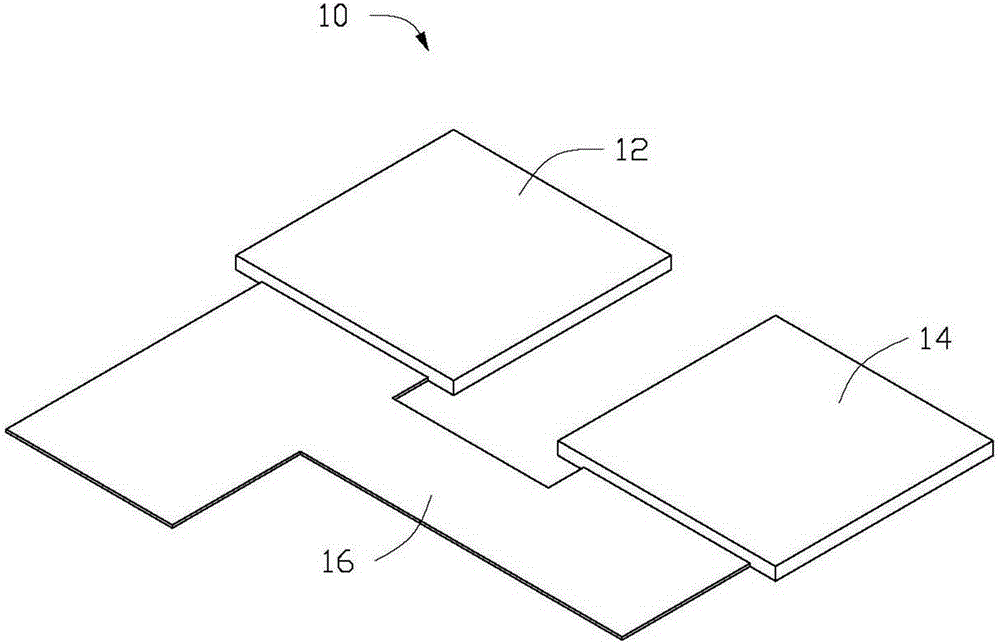
[0020] For a first step, see figure 1 , providing a flexible circuit board 10 .

[0021] The flexible circuit board 10 includes a first portion 12 , a second portion 14 and a connecting portion 16 . The shape and size of the first part 12 and the second part 14 are the same. In this embodiment, the first portion 12 and the second portion 14 are square. The first portion 12 and the second portion 14 are arranged in parallel and spaced apart, and the connecting portion 16 is used for connecting the first portion 12 and the second portion 14 . And the connecting portion 16 is connected to the same side of the first portion 12 and the second portion 14 .
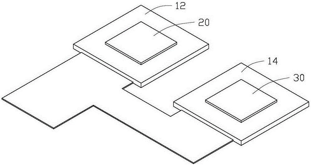
[0022] In ...


PUM


Abstract

The invention provides an imaging device comprising a flexible circuit board, and a first lens module and a second lens module arranged on the flexible circuit board, wherein the first lens module comprises a first side surface; the second lens module comprises a second side surface; the first side surface is dead against the second side surface; the first side surface is provided with a receiving part for accommodating glue; the first lens module and the second lens module are arranged on the flexible circuit board side by side; and the second side surface are attached to the receiving part arranged on the first side surface, and the second side surface and the receiving part are fixed together in mutual supporting by curing with the glue in the receiving part. The invention also provides an assembly method of the imaging device.

Description

technical field [0001] The invention relates to the field of optics, in particular to an imaging device and an assembly method thereof. Background technique [0002] The application of multi-camera module is to obtain the effect of virtual depth of field or resolution improvement by analyzing or superimposing the images obtained by multiple cameras. The direction of camera capture directly affects the image quality of post-processing. To ensure that multiple cameras face the same direction, it is necessary to actively align multiple camera modules. After the alignment is completed, multiple camera modules must be fixed to each other. However, in the existing fixing methods, whether the metal frame or the upper cover is used to fix the aligned cameras, additional components are required, thereby increasing the size of the multi-camera module. Contents of the invention [0003] In view of this, it is necessary to provide an assembly method for realizing simple alignment an...

Claims


Application Information

Patent Timeline
Patent Type & Authority Applications(China)
IPC IPC(8): H04N5/225G03B17/12G02B7/02
CPCG03B17/02G02B7/023G02B7/025H04N23/57H04N23/55H04N23/54H04N23/45
Inventor 许信彦
Owner TRIPLE WIN TECHSHENZHEN CO LTD
Why Eureka
Try Eureka