A depth recovery adjustment method and electronic equipment
A technology of electronic equipment and adjustment method, which is applied in the field of communication, and can solve problems such as overexposure of images, inability to restore depth, loss of image structured light features, etc.
- Summary
- Abstract
- Description
- Claims
- Application Information
AI Technical Summary
Problems solved by technology
Method used
Image
Examples
Embodiment 1
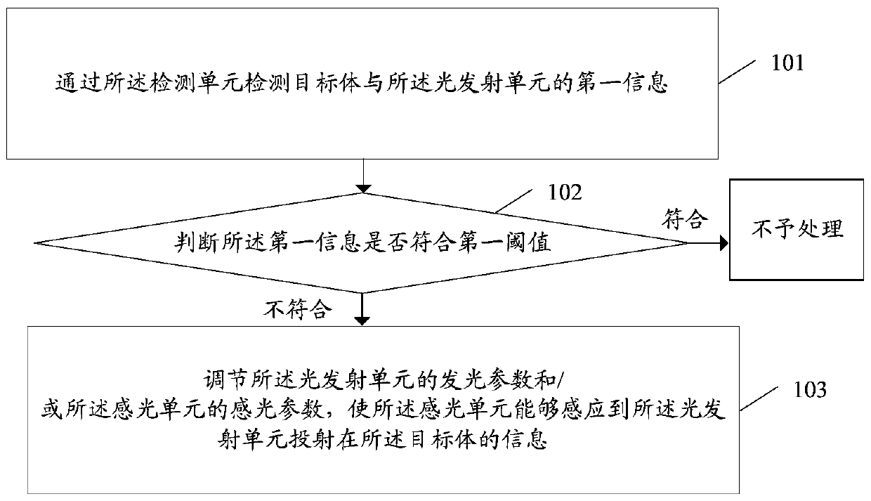
[0043] A depth recovery adjustment method in an embodiment of the present invention is applied to an electronic device, and the electronic device includes a detection unit, a light emitting unit, and a photosensitive unit, and the light emitting unit is projected on a target, such as figure 1 As shown, the method includes:
[0044] Step 101. Detecting the first information of the target object and the light emitting unit through the detection unit;
[0045] Step 102, judging whether the first information meets the first threshold, if not, execute step 103, otherwise, do not process;
[0046] Step 103. When the first information does not meet the first threshold, adjust the light emitting parameters of the light emitting unit and / or the light sensing parameters of the photosensitive unit, so that the photosensitive unit can sense the light emission The unit projects information on the target volume.
[0047] Adopting the embodiment of the present invention, through step 101, ...
Embodiment 2
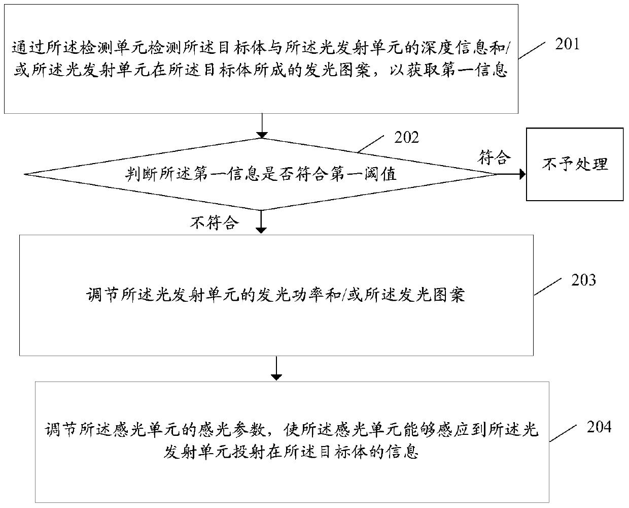
[0051] A depth recovery adjustment method in an embodiment of the present invention is applied to an electronic device, and the electronic device includes a detection unit, a light emitting unit, and a photosensitive unit, and the light emitting unit is projected on a target, such as figure 2 As shown, the method includes:
[0052] Step 201: Detect the depth information between the target object and the light emitting unit and / or the luminous pattern formed by the light emitting unit on the target object through the detection unit, so as to obtain first information;
[0053] Step 202, judging whether the first information meets the first threshold, if not, execute step 203, otherwise, do not process;
[0054]Step 203, when the first information does not meet the first threshold, adjust the light emitting power of the light emitting unit and / or the light emitting pattern;
[0055] Step 204 , when the first information does not meet the first threshold, adjust the light-sensin...
Embodiment 3
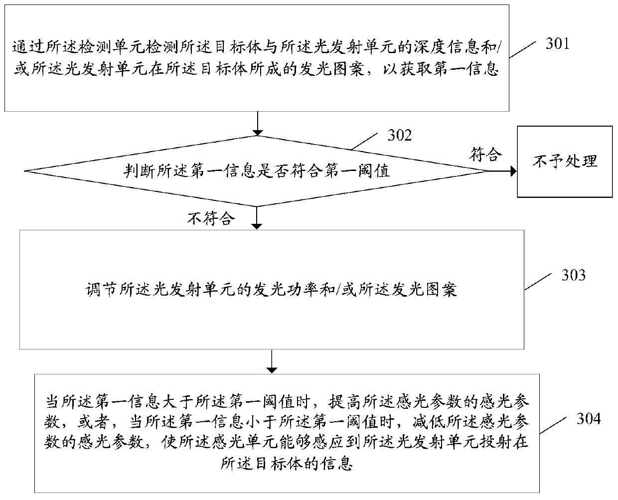
[0059] A depth recovery adjustment method in an embodiment of the present invention is applied to an electronic device, and the electronic device includes a detection unit, a light emitting unit, and a photosensitive unit, and the light emitting unit is projected on a target, such as image 3 As shown, the method includes:
[0060] Step 301: Detect the depth information between the target object and the light emitting unit and / or the light emission pattern formed by the light emitting unit on the target object through the detection unit, so as to obtain first information;
[0061] Step 302, judging whether the first information meets the first threshold, if not, execute step 303, otherwise, do not process;
[0062] Step 303. When the first information does not meet the first threshold, adjust the light emitting power of the light emitting unit and / or the light emitting pattern;
[0063] Step 304: When the first information is greater than the first threshold, increase the pho...
PUM
 Abstract
Description
Claims
Application Information
 - R&D
- Intellectual Property
- Life Sciences
- Materials
- Tech Scout
- Unparalleled Data Quality
- Higher Quality Content
- 60% Fewer Hallucinations
Browse by: Latest US Patents, China's latest patents, Technical Efficacy Thesaurus, Application Domain, Technology Topic, Popular Technical Reports.
© 2025 PatSnap. All rights reserved.Legal|Privacy policy|Modern Slavery Act Transparency Statement|Sitemap|About US| Contact US: help@patsnap.com


