A dynamic locking screw and dynamic locking bone plate system
A locking screw and bone plate technology, applied in the direction of outer plate, fixator, internal bone synthesis, etc., can solve the problems of complex production process of dynamic locking screw, and achieve the effect of easy callus formation, promotion of callus formation, and simple production process.
- Summary
- Abstract
- Description
- Claims
- Application Information
AI Technical Summary
Problems solved by technology
Method used
Image

Examples
Embodiment 1
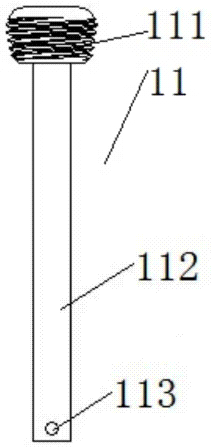
[0038] like Figure 1-Figure 3 As shown, this embodiment provides a dynamic locking screw, including a nail shaft 11 , a shaft sleeve 12 and a fixing pin 2 .
[0039] The screw shaft 11 includes a threaded portion 111, which is used to fix the dynamic locking screw on the bone plate through screw fit, and the threaded portion 111 can be in the shape of a dynamic locking screw in the prior art And structure, in this embodiment, the threaded part 111 is in the shape of an inverted truncated cone, and the thread on the threaded part 111 is a tapered thread; at the same time, the said threaded part 11 is connected with a shaft 112, There are many ways to connect the threaded part 111 and the shaft 112, such as threaded screw fixing, welding, etc. In this embodiment, the two are integrally formed; The end portion of 111 is provided with a first pin hole 113 .
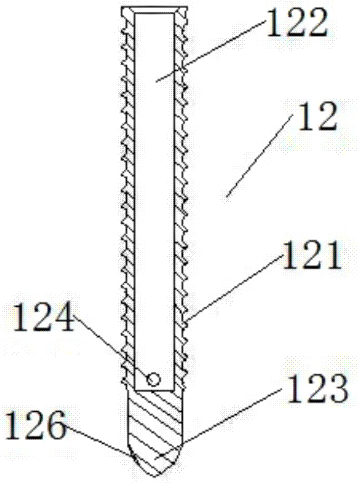
[0040] The shaft sleeve 12, the shaft sleeve 12 includes a shaft sleeve body, the outer body of the shaft sleeve body is...
Embodiment 2
[0046] like Figure 4-6 As shown, this embodiment provides a dynamic locking screw, which is a modification on Embodiment 1, and the modification is as follows:
[0047] The end of the shaft 112 away from the threaded portion 111 is provided with a fixing block 114, and the first pin hole 113 is arranged on the fixing block 114; the bottom end of the blind hole 122 is provided with a fixing groove 125 , and the second pin hole 124 is set on the groove wall of the fixing groove 125; One pin hole 113 and the second pin hole 124 fix the nail shaft 11 and the bushing 12 together; in this embodiment, the fixing block 114 is a square block, and the fixing Groove 125 matches with described fixed block 114, and its shape, size are consistent with described fixed block 114, can guarantee best fixing effect like this; In addition, in the present embodiment, as Image 6 As shown, the fixing pin 2 is a conical body with a circular cross section.
Embodiment 3
[0049] like Figure 7 As shown, this embodiment provides a dynamic locking bone plate system, including a bone plate 3, and the dynamic locking screw 1 of the present invention, the bone plate is any existing bone plate that can use dynamic locking screws, on which An internally threaded hole matched with the threaded part 111 is provided, which is suitable for installing and fixing the dynamic locking screw 1 to the fracture site. The number of the internally threaded holes can be determined according to the actual situation. In this embodiment, The number is 8, and the internal threaded hole is an internal taper threaded hole.
PUM
 Abstract
Description
Claims
Application Information
 - R&D
- Intellectual Property
- Life Sciences
- Materials
- Tech Scout
- Unparalleled Data Quality
- Higher Quality Content
- 60% Fewer Hallucinations
Browse by: Latest US Patents, China's latest patents, Technical Efficacy Thesaurus, Application Domain, Technology Topic, Popular Technical Reports.
© 2025 PatSnap. All rights reserved.Legal|Privacy policy|Modern Slavery Act Transparency Statement|Sitemap|About US| Contact US: help@patsnap.com