Multifunctional locking mechanism for sand core and core manufacturing method

A locking mechanism and multi-functional technology, applied in the field of casting molds, can solve problems such as the inability to meet the requirements of new core-making equipment, and achieve the effects of improving operation controllability, stable and reliable process, and small damage to sand cores

Active Publication Date: 2016-02-24
GUANGXI YUCHAI MASCH CO LTD
View PDF5 Cites 3 Cited by
  • Summary
  • Abstract
  • Description
  • Claims
  • Application Information

AI Technical Summary

Problems solved by technology

However, the traditional cold box mold does not have a structure that can realize the ...

Method used


Image

  • Multifunctional locking mechanism for sand core and core manufacturing method
  • Multifunctional locking mechanism for sand core and core manufacturing method
  • Multifunctional locking mechanism for sand core and core manufacturing method

Examples


Embodiment 1

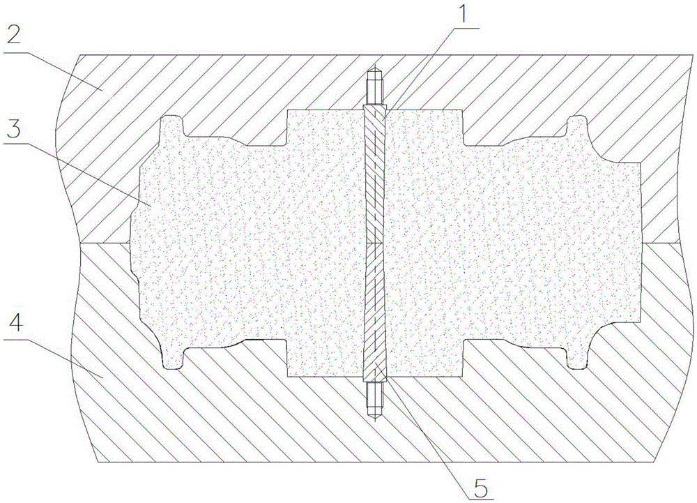
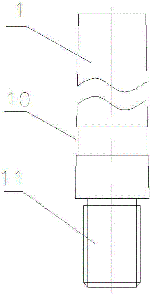
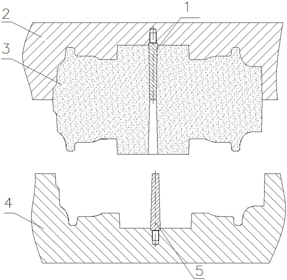
[0036] Such as Figure 1 ~ Figure 4 as well as Figure 9 As shown, a multi-functional sand core locking mechanism includes an upper core box 2 and a lower core box 4, the first group of core screw hole patterns 1 are vertically arranged in the upper core box 2, and the lower core box 2 is vertically arranged. Inside the core box 4, there is a second group of core screw hole patterns 5 arranged vertically. The first group of core screw hole patterns 1 is also provided with a position close to the upper core box 2 for locking and fixing the sand core 3 on the The groove 10 on the upper core box 2, the first set of core screw hole pattern 1 has a draft angle. In this embodiment, the groove 10 is an annular groove.

[0037] Specifically, the depth of the groove 10 is 0.4 mm, the height of the groove 10 is 8 mm, and the draft angle of the first core screw hole pattern 1 is 1°. Specifically, the draft angle of the first group of core screw hole patterns 1, the depth of the groove...

Embodiment 2

[0048] This embodiment is substantially the same as Embodiment 1, except that the depth of the groove 10 is 0.6 mm, the height of the groove 10 is 10 mm, and the draft angle of the first group of core screw hole pattern 1 is Angle is 2°, and the draft angles of the second group of core screw hole pattern 5, upper core box 2 and lower core box 4 are 2° respectively.

[0049] Through 100 sets of repeated tests, it was confirmed that the multi-functional sand core locking mechanism did not fall off when the lower core box 4 was ejected, and the sand core damage rate was 0 when the upper core box 2 was ejected.

Embodiment 3

[0051] This embodiment is substantially the same as Embodiment 1, except that the depth of the groove 10 is 0.9 mm, the height of the groove 10 is 12 mm, and the draft angle of the first group of core screw hole pattern 1 is Angle is 3°, and the draft angles of the second group of core screw hole pattern 5, upper core box 2 and lower core box 4 are 3° respectively.

[0052] Through 100 sets of repeated tests, it was confirmed that the multi-functional sand core locking mechanism did not fall off when the lower core box 4 was ejected, and the sand core damage rate was 0 when the upper core box 2 was ejected.


PUM

PropertyMeasurementUnit
Depthaaaaaaaaaa
Heightaaaaaaaaaa
Draft angleaaaaaaaaaa

Abstract

The invention discloses a multifunctional locking mechanism for a sand core. The mechanism comprises an upper core box and a lower core body, wherein a first core assembly screw hole die pattern is vertically arranged in the upper core box; a second core assembly screw hole die pattern is vertically arranged in the lower core box; at least one groove for locking and fixing the sand core on the upper core box is formed at a position, close to the upper core box, on the first core assembly screw hole die pattern; the first core assembly screw hole die pattern has pattern lifting inclination. With the adoption of the multifunctional locking mechanism for the sand core, the sand core can be well fixed during the die releasing process, and core assembly screw holes can be formed in the die-released sand core. The invention further provides a core manufacturing method using the aforementioned multifunctional locking mechanism for the sand core.

Description

technical field [0001] The invention relates to the field of casting moulds, in particular to a multifunctional sand core locking mechanism for making core box molds with sand cores. In addition, the invention also discloses a core making method using the multifunctional sand core locking mechanism. Background technique [0002] The cold box mold is the most commonly used mold in casting molds, and its function is to produce sand cores that meet the requirements in the casting production process. Cold box molds are generally installed on the core making machine and work in coordination with the core making machine. Because the core making machine is different, the core making principle is also different, so the requirements for the mold interface are also different. [0003] As the market demand for large marine machinery is increasing, the output of large marine machinery is also increasing. In order to improve the production and quality of large-scale marine engine bodie...

Claims


Application Information

Patent Timeline
IPC IPC(8): B22C21/14B22C9/10
CPCB22C9/10B22C21/14
Inventor 杨基谢永泽马国胜张俊许振冲王浩宁科明马武彬
Owner GUANGXI YUCHAI MASCH CO LTD
Why Eureka
Try Eureka