
Electron beam composite narrow gap mag welding method for large thickness martensitic heat-resistant steel separator

A welding method and electron beam welding seam technology, which is applied in the field of electron beam composite narrow gap MAG welding of large-thickness martensitic heat-resistant steel partitions, can solve the problems of difficult to guarantee welding quality, difficulty in obtaining satisfactory weld seam, and difficulty in weld seam formation To achieve the effect of improving welding quality, shortening welding operation time, and reducing weld seam offset

Active Publication Date: 2017-07-28
DONGFANG TURBINE CO LTD
View PDF9 Cites 0 Cited by
  • Summary
  • Abstract
  • Description
  • Claims
  • Application Information

AI Technical Summary

Problems solved by technology

The narrow-gap MAG welding method is prone to problems such as difficult weld formation and cleaning due to the large and deep groove, large welding volume, large welding deformation, and difficult to guarantee welding quality; Thick welding needs to use high pressure and large beam current to obtain thin and long welding beam to obtain effective penetration, but martensite is very susceptible to the influence of magnetic field to generate residual magnetism, which will make the electron beam deviate during the welding process and thus Cause problems such as unfused roots, making it difficult to obtain a satisfactory weld

Method used


Image

  • Electron beam composite narrow gap mag welding method for large thickness martensitic heat-resistant steel separator
  • Electron beam composite narrow gap mag welding method for large thickness martensitic heat-resistant steel separator
  • Electron beam composite narrow gap mag welding method for large thickness martensitic heat-resistant steel separator

Examples


Embodiment 1

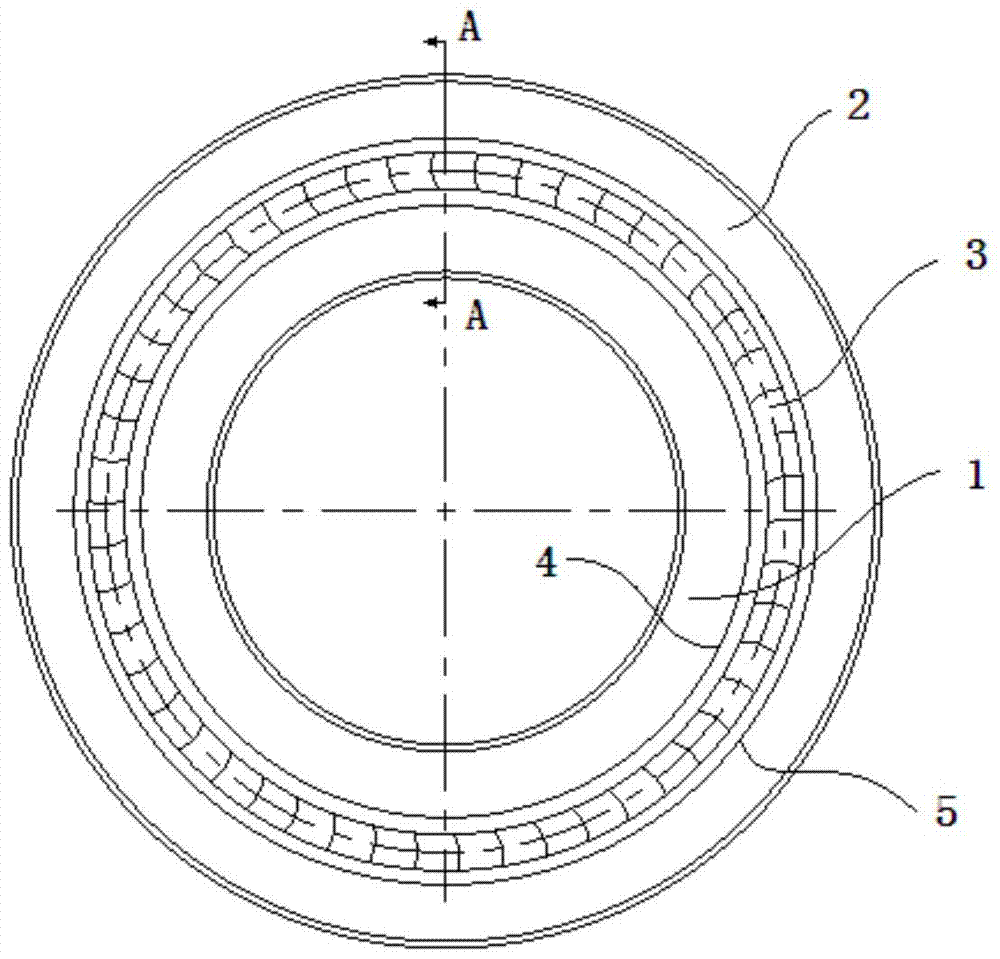
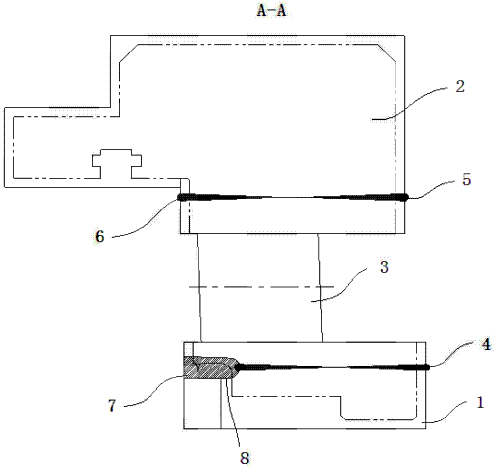
[0028] Such as figure 1 , figure 2 and image 3 As shown, the electron beam composite narrow-gap MAG welding method for large-thickness martensitic heat-resistant steel separators includes the following steps:

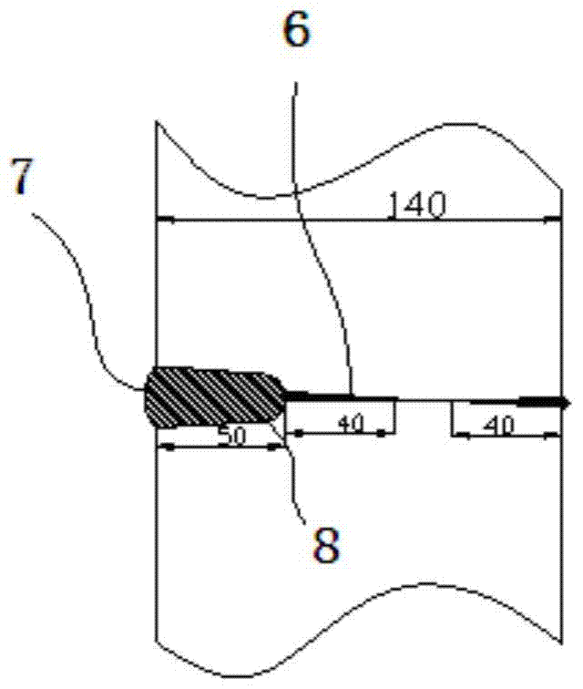
[0029] 1) According to the total depth of the main welding seam of the partition is 140mm, allocate the depth of the electron beam welding seam 6 and the narrow gap welding seam 7 to ensure that the depth of the electron beam welding seam 6 is 40mm, and distribute at the same time on both sides. A 50mm narrow gap and a deep U-shaped groove 8 are opened on the outer side of the beam weld 6;

[0030] 2) Assemble the diaphragm body 1, cascade 3 and diaphragm outer ring 2 on the assembly platform, adjust the gap to meet the design requirements, and clamp it with tooling to ensure that the diaphragm body 1, cascade 3 and diaphragm outer ring 2 are relatively fixed ;

[0031] 3) Detect the residual magnetism within 5mm of the inner and outer circle of the part to be wel...

Embodiment 2

[0040] Such as figure 1 , figure 2 and Figure 4 As shown, a large-thickness martensitic heat-resistant steel separator electron beam composite narrow-gap MAG welding method includes the following steps:

[0041] 1) According to the total depth of the main welding seam of the partition is 210mm, the depth of the electron beam welding seam 6 and the narrow gap welding seam 7 is allocated to ensure that the depth of the electron beam welding seam 6 is 50mm, and both sides are allocated at the same time. Deep U-shaped grooves 8 with narrow gaps of 50mm are respectively opened on the outer sides of the electron beam welds 6;

[0042] 2) Assemble the diaphragm body 1, cascade 3 and diaphragm outer ring 2 on the assembly platform, adjust the gap to meet the design requirements, and clamp it with tooling to ensure that the diaphragm body 1, cascade 3 and diaphragm outer ring 2 are relatively fixed ;

[0043] 3) Detect the residual magnetism within 5mm of the inner and outer circ...


PUM


Abstract

The invention discloses a method for electron beam composite narrow-gap MAG welding of a large-thickness martensitic heat-resistant steel partition, which is characterized in that it includes the following steps: 1) according to the total depth of the main welding seam of the partition, distribute the electron beam welding seam and the narrow gap For the depth of the gap weld, open a narrow gap and deep U-shaped groove on the outside of the electron beam weld; 2) Assemble the fixed partition body, blade grid and outer ring of the partition, and adjust the gap; 3) Detect and process the assembled partition 4) put it into the vacuum chamber to evacuate; 5) start the electron beam welding machine to carry out electron beam welding on the weld seam; 6) weld the back of the partition; 7) transfer the partition that has completed electron beam welding to the narrow Gap welding platform; 8) Perform MAG welding after preheating and cleaning the groove and nearby dirt; 9) After completing MAG welding, perform stress relief heat treatment. For the welding of large-thickness martensitic heat-resistant steel separators, the method has excellent welding quality, less welding consumables, short working time, simple operation and low repair rate.

Description

technical field [0001] The invention relates to a steam turbine partition, in particular to a large-thickness martensitic heat-resistant steel partition electron beam composite narrow-gap MAG welding method. Background technique [0002] The steam turbine diaphragm is the main part of the steam turbine. It is divided into a brush-fitted diaphragm, a shroud-type diaphragm and a direct-welded diaphragm. The brush-fitted diaphragm and the shroud-type diaphragm involve Welding of the outer ring of the partition. With the development of steam turbine technology, the initial steam pressure and temperature continue to increase, more heat-resistant martensitic steel is used as the material of the diaphragm, and the thickness of the diaphragm also increases, so that the main weld of the diaphragm (cascade and diaphragm body, Welding seams between the outer rings of the separators) have more prominent welding quality problems. The narrow-gap MAG welding method is prone to problems s...

Claims


Application Information

Patent Timeline
Patent Type & Authority Patents(China)
IPC IPC(8): B23K9/173
CPCB23K9/173B23K2103/04
Inventor 赵鹏飞钟杰梁钢舒学芳张从平谭小平匡清华罗军王喆王大勇裴金廷梁世均刘友东杨建平黄丽宋永辉张海波徐顺鑫宋渊毛桂军何芬
Owner DONGFANG TURBINE CO LTD
Learn More