Circular seam laser welding jig for thin-walled aluminum alloy end socket flange plates

A technology of laser welding jig and aluminum alloy, which is applied in the direction of laser welding equipment, welding equipment, welding equipment, etc., can solve the problems that the welding seam precision cannot meet the welding requirements, and the welding deformation is large, so as to achieve small welding deformation, low manufacturing cost, The effect of easy operation

Inactive Publication Date: 2014-06-04
HARBIN INST OF TECH
View PDF4 Cites 16 Cited by
  • Summary
  • Abstract
  • Description
  • Claims
  • Application Information

AI Technical Summary

Problems solved by technology

[0006] The present invention solves the problem that there is no special fixture for the laser welding of the flange ring seam of the thin-walled aluminum alloy head, which leads to large welding deformation and the weld seam precision cannot meet the welding requirements, and further provides a thin-walled aluminum alloy head method Lanpan ring seam laser welding fixture

Method used


Image

  • Circular seam laser welding jig for thin-walled aluminum alloy end socket flange plates
  • Circular seam laser welding jig for thin-walled aluminum alloy end socket flange plates
  • Circular seam laser welding jig for thin-walled aluminum alloy end socket flange plates

Examples


specific Embodiment approach 1

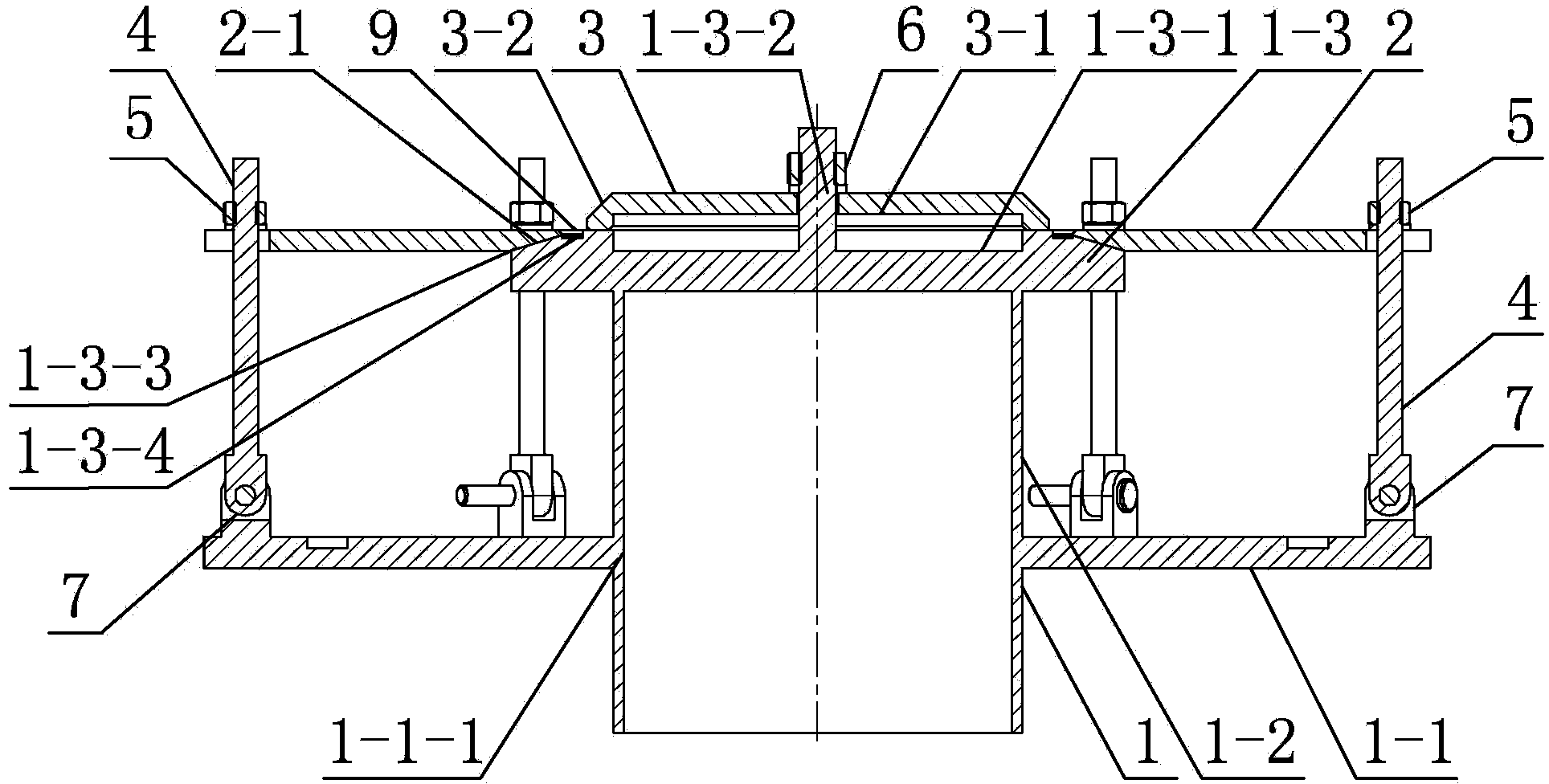
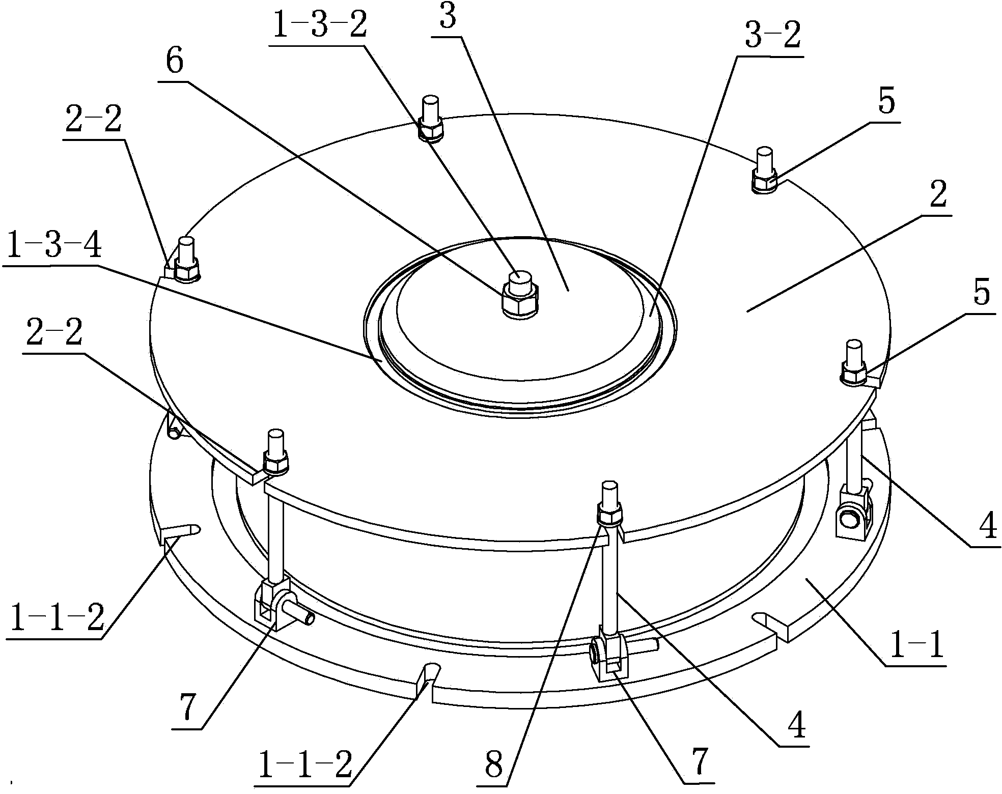
[0014] Specific implementation mode one: as Figure 1~4 As shown, the thin-walled aluminum alloy head flange circular seam laser welding fixture of this embodiment includes a bottom placenta 1, an outer pressure plate 2, an inner pressure plate 3, a first nut 6, a plurality of screws 4, a plurality of second Nuts 5 and a plurality of hinged seats 7; the bottom placenta 1 includes a lower disc 1-1, a cylinder 1-2 and an inner pressure disc seat 1-3, and a first central through hole 1-1 is processed on the disc 1-1 -1, the disc 1-1 is fixedly set in the middle of the outer wall of the cylinder 1-2, the inner pressure disc seat 1-3 is fixed on the upper end surface of the cylinder 1-2, the lower disc 1-1, the cylinder 1-2 and the inner pressure plate seat 1-3 are coaxially arranged and the three are integrated, and the upper end surface of the inner pressure plate seat 1-3 is processed with a first circular central groove 1-3-1, the first circular The upper end surface of the ce...

specific Embodiment approach 2

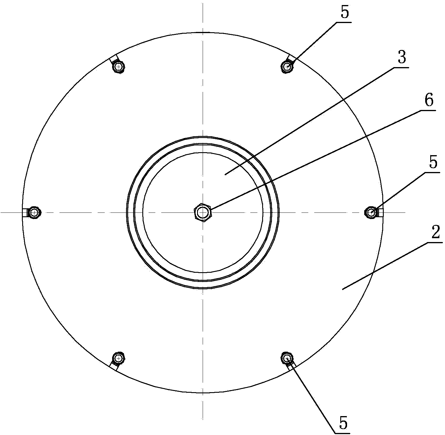
[0016] Specific implementation mode two: as Figure 2~4 As shown, there are six screw rods 4 , second nuts 5 and hinge seats 7 in this embodiment. In this design, the number of screw rod 4, second nut 5 and hinge seat 7 is six, and the force of each second nut 5 is the same, so that the force on the head is uniform, and the welding deformation of the ring seam of the flange of the head can be controlled. . Other components and connections are the same as those in the first embodiment.

specific Embodiment approach 3

[0017] Specific implementation mode three: as figure 1 with image 3 As shown, in this embodiment, an annular groove 1-3-4 is processed on the inner pressure plate seat 1-3 along the circumferential direction, and the annular groove 1-3-4 is located at the annular gap 9 . Such a design is to prevent the occurrence of weld leakage caused by the serious sagging of the weld seam, thereby ensuring the formation of the weld seam. Other compositions and connections are the same as those in Embodiment 1 or 2.


PUM


Abstract

The invention relates to a welding jig, in particular to a circular seam laser welding jig for thin-walled aluminum alloy end socket flange plates. The circular seam laser welding jig aims to solve the problems that as no special circular seam laser welding jig for the thin-walled aluminum alloy end socket flange plates exists in the prior art, welding deformation is serious, and the welding accuracy cannot meet the welding requirement. An inner platen is located at the upper end face of an inner platen base, a first circular center groove corresponds to a second circular center groove in an up-and-down mode, a first annular groove is machined in the upper end face of the outer edge of the inner platen base in the circumferential direction, a second annular groove is formed in the lower end face of the inner ring of an outer platen in the circumferential direction, the second annular groove of the outer platen is combined with the first annular groove in a pressed mode, an annular interval is reserved between the outer platen and the inner platen, a plurality of hinge bases are evenly distributed and fixedly installed at the outer edge of a lower disc in the circumferential direction, the lower end of each screw rod is hinged to the corresponding hinge base, and the upper end of each screw rod penetrates through the outer edge of the outer platen and is in threaded connection with a second nut. The circular seam laser welding jig is used for welding the thin-walled aluminum alloy end socket flange plates.

Description

technical field [0001] The invention relates to a laser welding jig for a ring seam of a flange, in particular to a laser welding jig for a ring seam suitable for a flange of a thin-walled aluminum alloy head. Background technique [0002] With the continuous development of economy and science and technology, my country's aerospace field is developing rapidly, and its performance requirements for key components are also more stringent. The aluminum alloy head flange used in aerospace is a key component of fuel tanks on rockets, missiles, and aircraft, and its performance is of great significance to the devices in service. [0003] The existing head flange welding usually adopts manual TIG welding, the production efficiency is low, and the welding quality is also directly related to the technical level of the welding workers. The stability of the weld quality cannot be guaranteed, and there are serious safety hazards. As an emerging welding technology, laser welding technolo...

Claims


Application Information

Patent Timeline
Patent Type & Authority Applications(China)
IPC IPC(8): B23K37/04B23K26/70
CPCB23K26/0823B23K26/702
Inventor 雷正龙刘鸣陈彦宾杨雨禾胡雪
Owner HARBIN INST OF TECH
Why Eureka
Try Eureka