Tube body supporting structure used for tube body cutting device

A technology of cutting device and supporting structure, applied in the direction of positioning device, support, clamping, etc., can solve the problems of bracket pressure deviation, sliding sleeve stuck on the column, affecting production or cutting efficiency, etc., and achieve smooth lifting and moving. Effect

Inactive Publication Date: 2016-02-24
韩功篑
View PDF7 Cites 2 Cited by
  • Summary
  • Abstract
  • Description
  • Claims
  • Application Information

AI Technical Summary

Problems solved by technology

[0002]For real-time production of pipe fittings or cutting of pipe fittings, it will involve real-time online support of pipe fittings to keep the axis of pipe fittings in a horizontal state. In the technology, a bracket structure that can be lifted and lowered along the column is used to realize it, that is, a column is set on the left and right sides, and a sliding sleeve is set on the bracket. The height of the bracket, but this structure also has certain defects. When the center of the pipe fittings is not aligned or the wall thickness is uneven, the bracket will be biased off, and when the height of the bracket is adjusted again, it will appear If the sliding sleeve is stuck on the column, it needs to be stopped for adjustment, which seriously affects the efficiency of production or cutting

Method used


Image

  • Tube body supporting structure used for tube body cutting device
  • Tube body supporting structure used for tube body cutting device
  • Tube body supporting structure used for tube body cutting device

Examples


Embodiment Construction

[0016] Below in conjunction with the embodiment shown in the accompanying drawings, the present invention is described in detail as follows:

[0017] The left and right directions in this specification refer to the left and right directions when viewed along the direction in which the pipe body moves.

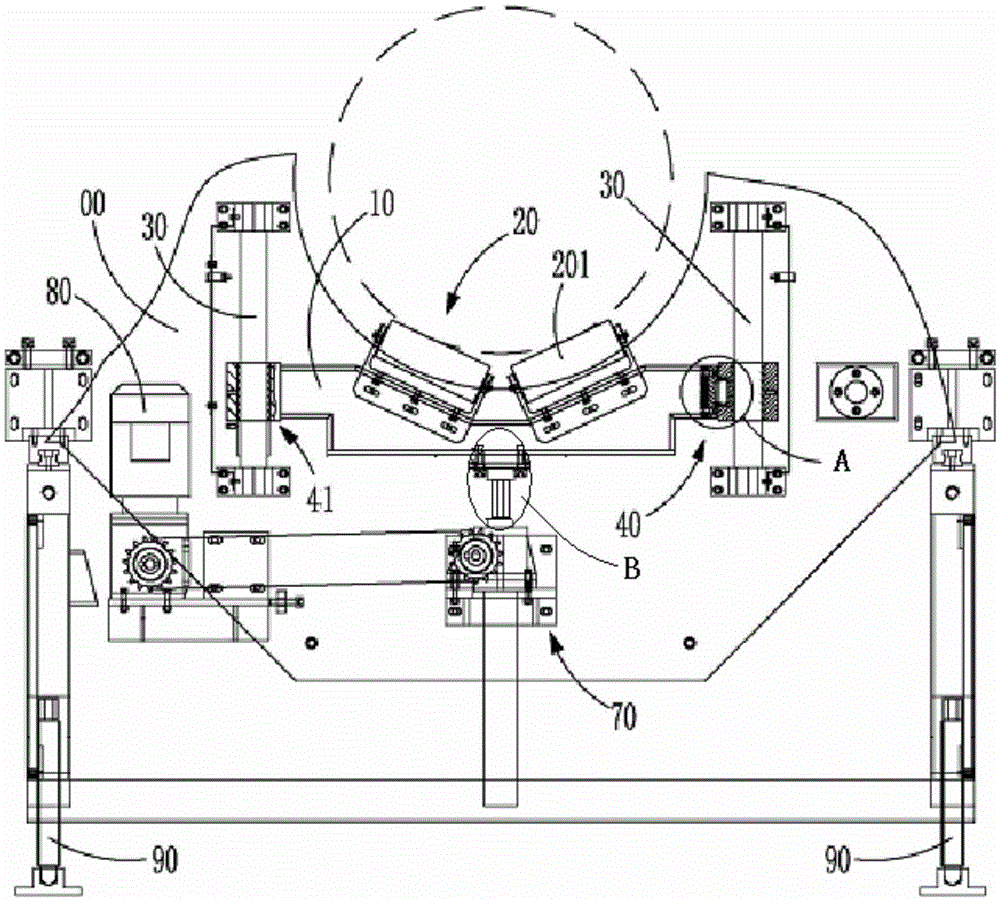
[0018] as attached figure 1 , 2 As shown, a pipe body support structure used by a pipe body cutting device includes a frame 00, a bracket 10 that can be lifted and lowered on the frame 00, and a bracket 10 that is set on the bracket 10. The idler assembly 20 supporting the pipe body, the frame 00 is provided with two guide columns 30 along the vertical direction, and the left and right sides of the bracket 10 are respectively provided with guide columns capable of moving along the corresponding guide columns. 30 moves the first sliding sleeve 40 and the second sliding sleeve 41, the first sliding sleeve 40 or the second sliding sleeve 41 is connected to the bracket 10 through...


PUM


Abstract

The invention discloses a tube body supporting structure used for a tube body cutting device. A ball-head ball-socket structure is arranged between a bracket and a sliding sleeve capable of sliding on a stand column; when the bracket is lifted and moved again, the structure can regulate the direction of acting force, on the stand column, of the sliding sleeve, so that the sliding sleeve smoothly moves along the stand column, thereby avoiding blocking; a lead screw and the bracket are movably connected through a head part capable of deflecting and moving in a movable space, so that the stress direction of the bracket can be regulated by virtue of different acting positions, in the movable space, of the head part when the bracket deflects, and therefore, smooth lifting and moving of the bracket is realized.

Description

technical field [0001] The invention relates to a pipe support structure used in a pipe cutting device. Background technique [0002] For the pipe fittings produced in real time or when the pipe fittings are cut, real-time online support for the pipe fittings will be involved to keep the axis of the pipe fittings in a horizontal state. In the past, a bracket structure that can be lifted along the column is used. Realization, that is, a column is set on the left and right sides, and a sliding sleeve is set on the bracket. When in use, the height of the required bracket is adjusted according to the height of the axis of the pipe fitting and the radius of the pipe fitting. However, this structure also has certain defects. When the center of the pipe fittings is misaligned or the wall thickness is uneven, the bracket will be biased off, and when the height of the bracket is adjusted again, the sliding sleeve will be stuck on the column, and it is necessary to stop the machine fo...

Claims


Application Information

Patent Timeline
IPC IPC(8): B23Q3/02
CPCB23Q3/02
Inventor 韩功篑
Owner 韩功篑
Why Eureka
Try Eureka