Electromagnetic valve for low temperature pipeline

A low-temperature pipeline and solenoid valve technology, applied in the direction of lift valve, valve details, valve device, etc., can solve the problems of poor air circulation, large moving resistance of the valve disc, easy to be frozen, etc., to achieve smooth air circulation, up and down The effect of smooth movement and not easy to freeze

Active Publication Date: 2015-06-10
ZHANGJIAGANG FURUI SPECIAL EQUIP CO LTD
View PDF8 Cites 2 Cited by
  • Summary
  • Abstract
  • Description
  • Claims
  • Application Information

AI Technical Summary

Problems solved by technology

[0003] In the traditional solenoid valve, the valve disc has a relatively large resistance to movement in the valve body, and the air circulation is not smooth. When it is used in a low-temperature pipeline, it is easy to be frozen.

Method used


Image

  • Electromagnetic valve for low temperature pipeline
  • Electromagnetic valve for low temperature pipeline
  • Electromagnetic valve for low temperature pipeline

Examples


Embodiment Construction

[0021] The present invention will be further described now in conjunction with accompanying drawing. These drawings are simplified schematic diagrams only to illustrate the basic structure of the present invention in a schematic way, so they only show the components relevant to the present invention.

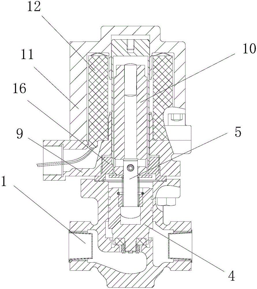
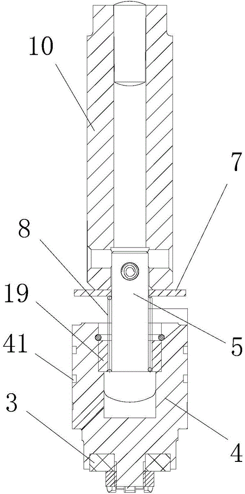
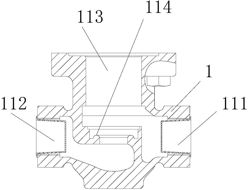
[0022] Such as figure 1 figure 2 image 3 As shown, a solenoid valve for cryogenic pipelines includes a valve body 1, a valve cover 9, a valve stem 5 and a valve disc 4, the valve cover 9 is arranged on the upper end of the valve body 1, the valve stem 5 is arranged in the valve cover 9, and the valve The disc 4 is set at the lower end of the valve stem 5, the valve disc 4 is movably set on the sealing surface of the valve port in the valve body 1, the valve cover 9 is provided with a pilot assembly 16, and the pilot assembly 16 is provided with an iron core 10 which can move up and down. The upper end of the valve stem 5 is connected to the iron core 10; the valve cover 9 i...


PUM


Abstract

The invention relates to an electromagnetic valve for a low temperature pipeline. The electromagnetic valve comprises a valve body, a valve cover, a valve rod and valve clacks. A pilot assembly is arranged on the valve cover, an iron core capable of moving vertically is arranged in the pilot assembly, the upper end of the valve rod is connected with the iron core, a protection cover is arranged on the outer portion of the valve cover, and an electromagnetic coil is arranged in the protection cover. A spring and a washer sleeve the valve rod. An inlet cavity, a valve clack cavity and an outlet cavity are arranged in the valve body. A valve port is formed in the valve body at the bottom of the valve clack cavity and communicated with the outlet cavity, and the side portion of the valve clack cavity is communicated with the inlet cavity. The valve clacks are arranged in the valve clack cavity, a gap is formed between the outer walls of the valve clacks and the inner wall of the valve clack cavity, and at least one annular groove is formed in the outer walls of the valve clacks. The gap is formed between the valve clacks and the inner wall of the valve clack cavity, so that valve clack moving resistance is reduced, vertical movement of the valve clacks is smooth, air circulation is smooth, freezing cannot happen easily, the electromagnetic valve is applicable to low temperature which can reach -196 DEG C, and the pressure can reach 2.5 MPa.

Description

technical field [0001] The invention relates to a solenoid valve for a cryogenic pipeline. Background technique [0002] Solenoid valves are often used in the intake pipeline of natural gas engines, mainly to cut off the gas supply to the engine in time. [0003] In traditional solenoid valves, the valve disc has relatively large resistance to movement in the valve body, and the air circulation is not smooth. When used in low-temperature pipelines, it is easy to be frozen. Contents of the invention [0004] The technical problem to be solved by the present invention is to overcome the deficiencies of the prior art and provide a solenoid valve for cryogenic pipelines. [0005] The technical solution adopted by the present invention to solve the technical problem is: a solenoid valve for cryogenic pipelines, including a valve body, a valve cover, a valve stem and a valve disc, the valve cover is arranged on the upper end of the valve body, and the valve stem is arranged In...

Claims


Application Information

Patent Timeline
Patent Type & Authority Applications(China)
IPC IPC(8): F16K31/06F16K1/36F16K1/46F16K1/48
CPCF16K1/36F16K1/46F16K1/48F16K27/029F16K31/0655F16K31/0675
Inventor 刘永平王瑞东胡晨曦周晓会张飞
Owner ZHANGJIAGANG FURUI SPECIAL EQUIP CO LTD
Why Eureka
Try Eureka