Clothes template machine stamping head convenient to use

A garment template machine and punching head technology, applied in metal processing and other directions, can solve the problems of long time, troublesome operation, and difficulty in disassembling and assembling tools, and achieve the effects of improving efficiency, saving time, and reducing the difficulty of replacing tools.

Inactive Publication Date: 2016-02-24
CHANGZHOU SINAJET SCI & TECH
View PDF0 Cites 2 Cited by
  • Summary
  • Abstract
  • Description
  • Claims
  • Application Information

AI Technical Summary

Problems solved by technology

[0003] In order to overcome the problems of difficulty in disassembling and assembling the tool of the existing punching head, long time and troublesome operation, the present invention provides a convenient punching head for garment template machine

Method used


Image

  • Clothes template machine stamping head convenient to use

Examples


Embodiment Construction

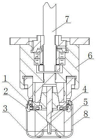
[0013] Such as figure 1 It is a schematic diagram of the structure of the present invention. It is a convenient stamping head for a garment template machine, including a base 6, a connecting rod 7, a pressing cover 3 and a punching knife 4. The connecting rod 7 is connected to the center of the base 6, and the punching knife 4 is connected to the At the bottom of the connecting rod 7, the pressing cover 3 is connected to the bottom of the base 6 and is set on the periphery of the punching knife 4. The base 6 is provided with a compression spring 1 and tongue core 2, and the pressing cover 3 is provided with a chute 8. The tongue core 2 is hook-shaped and is rotatably connected to both sides of the base 6 . The compression spring 1 is installed horizontally on the bottom of the base 6 and is stuck between the base 6 and the tongue core 2 . The return spring 5 is stuck between the base 6 and the pressing cover 3 . The chute 8 is symmetrically distributed on both sides of the ...


PUM


Abstract

The invention relates to the technical field of clothes template machines, in particular to a clothes template machine stamping head convenient to use. The clothes template machine stamping head comprises a base, a connecting rod, pressing covers and a stamping cutter. The connecting rod is connected to the center of the base. The stamping cutter is connected to the bottom of the connecting rod. The pressing covers are connected to the bottom of the base and arranged on the periphery of the stamping cutter in a sleeving manner. Compression springs and tongue cores are arranged on the base. The pressing covers are provided with sliding grooves. The hook-shaped tongue cores are arranged on the two sides of the base. Meanwhile, the sliding grooves are correspondingly formed in the two sides of the pressing covers, hook tips of the tongue cores are embedded in the sliding grooves, and a movable connecting mechanism is formed. The clothes template machine stamping head is convenient and fast to use, the difficulty of cutter replacing is greatly lowered, time is saved, and efficiency is improved.

Description

technical field [0001] The invention relates to the technical field of garment template machines, in particular to a punching head of a convenient garment template machine. Background technique [0002] At present, in the formwork machine industry, in order to complete the dust suction function, it is often necessary to install a dust suction sealing device around the milling cutter of the stamping head, which makes it difficult to install and replace the milling cutter, takes a long time, and is difficult to control the depth of the cutter. The milling cutter can only be installed after being removed, which is troublesome to operate. Contents of the invention [0003] In order to overcome the problems of difficulty in disassembling and assembling knives of the existing punching head, long time and troublesome operation, the invention provides a convenient punching head of a garment template machine. [0004] The technical solution adopted by the present invention to solv...

Claims


Application Information

Patent Timeline
Patent Type & Authority Applications(China)
IPC IPC(8): B26D7/26
Inventor 曹新成
Owner CHANGZHOU SINAJET SCI & TECH
Why Eureka
Try Eureka