Solid-liquid separator for sanitation vehicles

A technology of solid-liquid separator and sanitation vehicle, which is applied in the field of sanitation cleaning equipment, can solve the problems of untimely response of the clutch system, splashing of discharge material, and excessive discharge speed, etc., and achieve good solid-liquid separation effect and high separation efficiency High, good separation effect

Active Publication Date: 2017-01-04
HUNAN JINSONG AUTOMOBILE CO LTD
View PDF7 Cites 0 Cited by
  • Summary
  • Abstract
  • Description
  • Claims
  • Application Information

AI Technical Summary

Problems solved by technology

Due to the direct meshing transmission between the moving dial and the main shaft, this kind of solid-liquid separator is easy to cause the discharge of the material to splash under the action of the high-speed rotation of the main shaft. does not form a stable solid
Especially when the material contains gas, the separated material is still fluid, the separation effect is poor, the work efficiency is low, and it is inconvenient

Method used


Image

  • Solid-liquid separator for sanitation vehicles
  • Solid-liquid separator for sanitation vehicles

Examples


Embodiment Construction

[0022] The present invention is described in detail below in conjunction with accompanying drawing and specific embodiment:

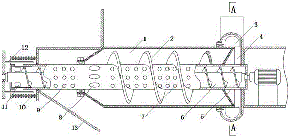
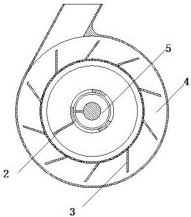
[0023] like figure 1 , figure 2 As shown, the solid-liquid separator for sanitation vehicles of the present invention includes a primary auger 5, a primary separation drum 6, a discharge device and a secondary separation drum 1. Both ends of the 5th shaft of the first-stage auger are movably connected with the casing through bearings, and one of the ends is connected with the power transmission shaft. The primary separation cylinder 6 is fixedly connected with the casing, and the primary separation cylinder 6 is divided into a feeding area, an exchange area and a recovery area in turn from the front end to the end. The front end of the primary separation cylinder 6 is sealed and is movably connected with the primary auger shaft through bearings; the cylinder wall of the feed zone is provided with a feed hole. The feeding hole can be connected with t...


PUM


Abstract

The invention discloses a solid-liquid separator for an environmental sanitation truck. The solid-liquid separator comprises a first-grade auger, a first-grade separation cylinder, a discharge device, a second-grade auger blade and a second-grade separation cylinder, wherein the first-grade separation cylinder is fixedly connected with a shell, is provided with a feed area, an exchange area and a recovery area in sequence, and coats the first-grade auger; the feed area is positioned at the front end of the first-grade separation cylinder, and is provided with a feed hole in the cylinder wall; the exchange area is positioned behind the feed area, and is provided with a grading hole in the cylinder wall; the recovery area is positioned behind the exchange area, and is provided with a recovery hole in the cylinder wall; the discharge device is positioned in an opening at the tail end of the first-grade separation cylinder for controlling the discharge of the first-grade separation cylinder; the cylinder wall of the second-grade separation cylinder is provided with a water filter hole, coats the exchange area and the recovery area of the first-grade separation cylinder,and is isolated from the feed area; and the inner wall of the second-grade separation cylinder and the outer wall of the first-grade separation cylinder are movably connected through a sealing bearing.

Description

technical field [0001] The invention relates to sanitation cleaning equipment, in particular to a solid-liquid separator for sanitation vehicles. Background technique [0002] The solid-liquid separator currently used is generally assembled by a moving dial, an auger and a clutch mechanism. The material moves axially under the pressure of the auger, and the moving dial overcomes the reaction force of the auger and moves a certain distance to mesh with the main shaft, and the auger drives the moving dial to rotate to complete the discharge action. This kind of solid-liquid separator is directly meshed with the main shaft due to the direct meshing transmission of the moving dial and the main shaft. Under the action of the high-speed rotation of the main shaft, it is easy to cause the discharge of the material to splash. Can not form a stable solid. Especially when the material contains gas, the separated material is still fluid, the separation effect is poor, the work effici...

Claims


Application Information

Patent Timeline
Patent Type & Authority Patents(China)
IPC IPC(8): B30B9/14B30B15/30B30B15/32
CPCB30B9/14B30B15/30B30B15/32
Inventor 李金松赵正义
Owner HUNAN JINSONG AUTOMOBILE CO LTD
Why Eureka
Try Eureka