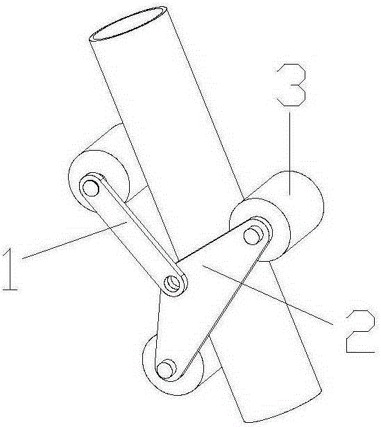
Closed high-altitude cable rope climbing robot
A robot and cable technology, which is applied in the field of cable-stayed bridge cable detection robot, can solve the problems that the driving wheel and the driven wheel have different obstacle-surmounting capabilities, the climbing ability is also greatly affected, and the internal force of the mechanism is large, so as to achieve the load capacity. Strong, good thermal stability, strong ability to overcome obstacles
- Summary
- Abstract
- Description
- Claims
- Application Information
AI Technical Summary
Problems solved by technology
Method used
Image
Examples
Embodiment 1
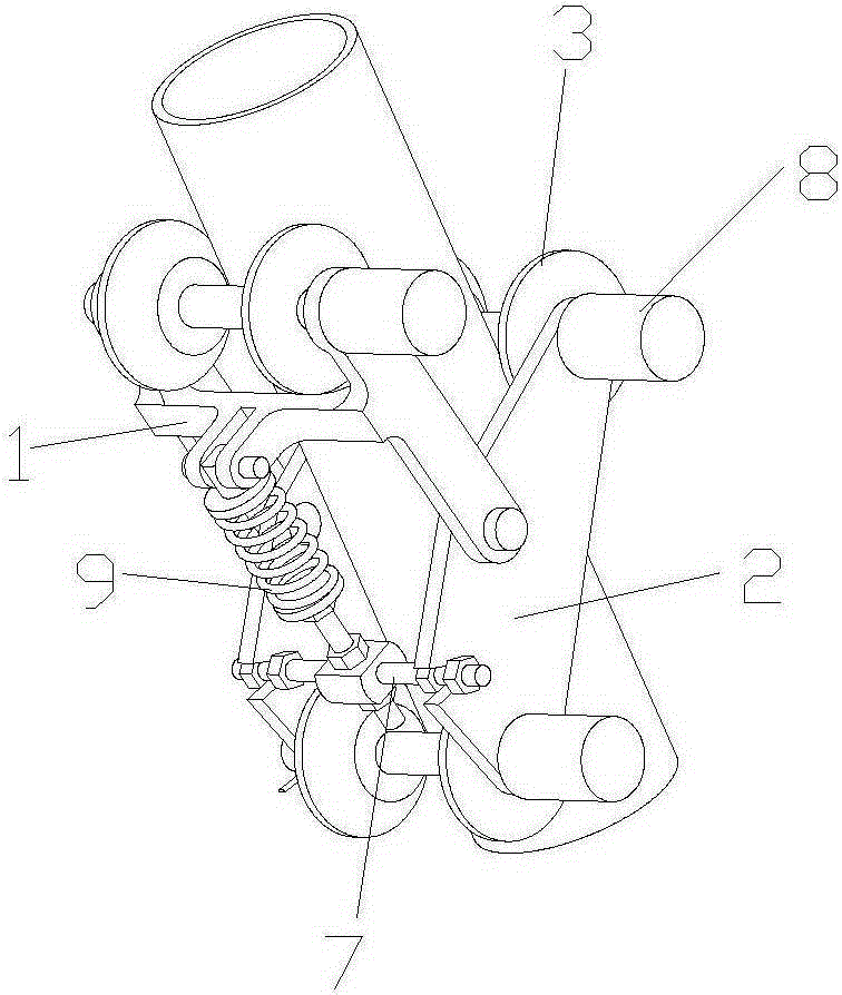
[0078] Such as Figure 4 , Figure 5 , Figure 6 and Figure 7 As shown, the descending speed limiting device includes a suspension 41 , a speed increaser 42 , a brake housing 46 , a brake rotor 43 , a centrifugal spring 45 and a centrifugal block 44 .
[0079] The brake rotor, the centrifugal spring and the centrifugal block are all arranged in the brake casing, the centrifugal block and the brake rotor are hinged, and the centrifugal spring is arranged between the centrifugal block and the brake rotor.
[0080] The fixed frame is arranged on the left side of the speed increaser, and is sleeved on the axle end of the wheel shaft, which is fixedly connected with the left input end of the speed increaser, and the output shaft end of the speed increaser is fixedly connected with the brake rotor. Wherein, the speed increaser may be set according to actual needs, and may not be present.
[0081] When the speed is low, the inertial force is small, and under the action of the sp...
Embodiment 2
[0083] Such as Figure 8 and Figure 9 As shown, the descending speed limiting device includes a stator 52 , an impeller 53 , a compression spring 54 , a fixed disc 51 , a ball valve 56 , a speed increaser 42 and an adjusting bolt 512 . The speed increaser can be set according to actual needs, and it is not necessary.
[0084] The speed increaser 42 , the stator 52 , the fixed plate 51 and the adjusting bolt 512 are sequentially coaxially sleeved on the outer periphery of the axle end 21 of the wheel shaft.
[0085] A side of the fixed disk 51 adjacent to the stator 52 is provided with several conical valve cores 511 along the circumferential direction, preferably two.
[0086] Such as Figure 10 As shown, the stator 52 is sequentially provided with a hydraulic chamber 521 , an inner blind hole 522 and an outer blind hole 523 which communicate with each other from the inside to the outside; the hydraulic chamber 521 is provided with an impeller 53 set on the axle end 21 of ...
Embodiment 3
[0089] Such as Figure 11 As shown, the descending speed limiting device also includes a rotor 57 and an inertia block 58 in addition to all the components in Embodiment 2. The rotor 57 is sleeved on the axle shaft end 21 on the right side of the fixed disk 51 . The left side of the rotor is provided with several inclined chute 571 along the circumferential direction, and each inclined chute 571 is provided with an inertia block 58 , and each inertia block 58 has an inclined surface 581 matched with the inclined chute 571 .
[0090] When the fluid flows through the above-mentioned damping holes, resistance is generated, and the magnitude of the resistance is related to the opening degree of the damping holes. When rising, the fluid passes through the inner blind hole and flows from the right side of the steel ball to the left side, and the damping hole has no effect. When descending, the inner blind hole is cut off by the steel ball (effect of spring force), the fluid passes...
PUM
 Abstract
Description
Claims
Application Information
 - R&D
- Intellectual Property
- Life Sciences
- Materials
- Tech Scout
- Unparalleled Data Quality
- Higher Quality Content
- 60% Fewer Hallucinations
Browse by: Latest US Patents, China's latest patents, Technical Efficacy Thesaurus, Application Domain, Technology Topic, Popular Technical Reports.
© 2025 PatSnap. All rights reserved.Legal|Privacy policy|Modern Slavery Act Transparency Statement|Sitemap|About US| Contact US: help@patsnap.com


