Microwave darkroom test system based on wireless control and wireless control method

A wireless control, microwave anechoic chamber technology, applied in the direction of measuring electricity, measuring devices, measuring electrical variables, etc., can solve the problem of inability to achieve multi-path loss in microwave anechoic chamber, and achieve low-cost effects

Inactive Publication Date: 2016-02-24
CNGC INST NO 206 OF CHINA ARMS IND GRP
View PDF4 Cites 7 Cited by
  • Summary
  • Abstract
  • Description
  • Claims
  • Application Information

AI Technical Summary

Problems solved by technology

[0012] 3. Existing test equipment cannot realize the test problem of multi-path loss in microwave anechoic chamber

Method used


Image

  • Microwave darkroom test system based on wireless control and wireless control method
  • Microwave darkroom test system based on wireless control and wireless control method
  • Microwave darkroom test system based on wireless control and wireless control method

Examples


Embodiment Construction

[0032] Now in conjunction with embodiment, accompanying drawing, the present invention will be further described:

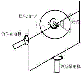
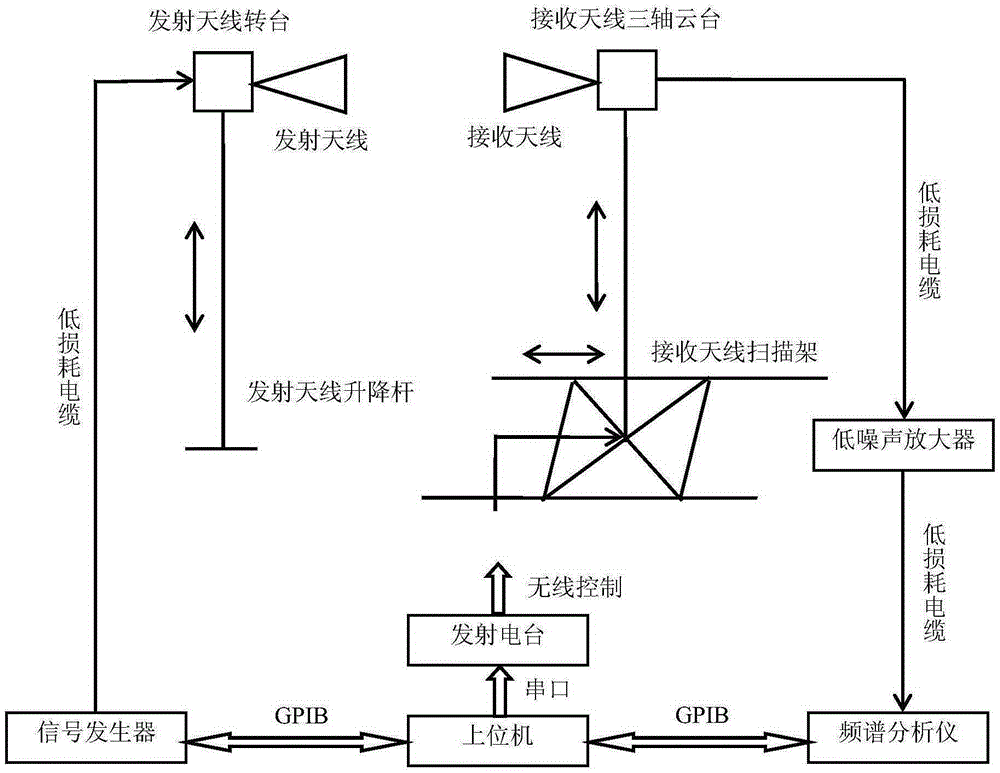
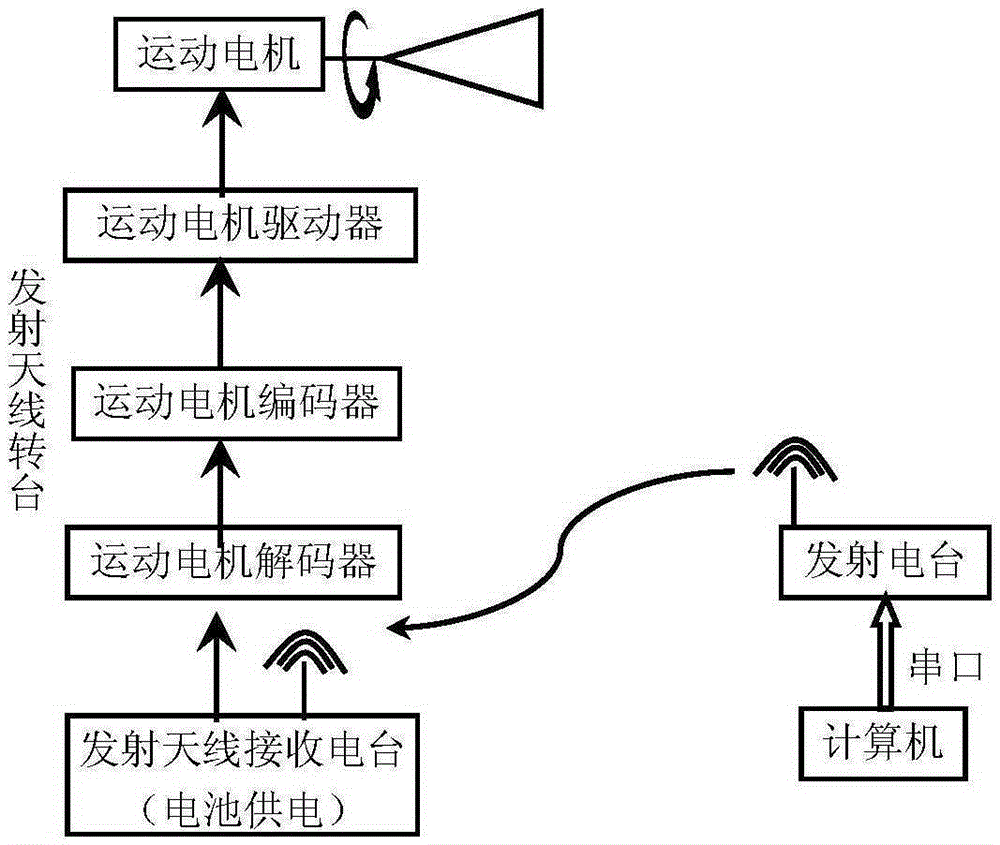
[0033] The working principle of the present invention is as follows: the upper computer communicates with the transmitting station through the serial port 485, and the serial port 485 can communicate over a long distance, so that testers can control the test equipment in the control room of the microwave darkroom or other places far away from the quiet area of ​​the microwave darkroom, reducing personnel and testing Effect of equipment on darkroom test results. The upper computer communicates with the serial port 485, and sends the control information of each axis motor through the transmitting station. The transmitting antenna receiving station converts the control command into the transmitting motor motion control command through the decoder, and controls the motor movement through the encoder, so that the transmitting antenna is on the polarization plane. At t...


PUM


Abstract

The invention relates to a microwave darkroom test system based on wireless control and a wireless control method. A host computer communicates with an emission radio station via a 485 serial port, motion control instructions of axial motors are transmitted to an emission antenna reception radio station, a three-axis holder reception radio station and a reception radio station of a reception antenna scanning rack via a radio station, and the emission antenna reception radio station, the three-axis holder reception radio station and the reception radio station of the reception antenna scanning rack convert the control instructions into a system five-dimensional motion control instruction via decoders, and controls motion of the motors via encoders of themselves. Five-dimension, including horizontal, vertical, oriented, pitching and polarized, movement of the reception antenna as well as the polarized movement of the emission antenna can be completed, and requirements for microwave darkroom test can be met.

Description

technical field [0001] The invention belongs to electromagnetic field and microwave technology, specifically relates to the technical field of microwave darkroom performance testing, and is mainly used for the acceptance test of newly-built microwave darkrooms. Background technique [0002] The main function of the microwave anechoic chamber is to simulate free space without reflection, and the maximum reflection level in the quiet zone is its most important technical index. This test method adopts the free space standing wave ratio method. It is to place the transmitting antenna at one end (front end) of the anechoic chamber, and place the receiving antenna in the quiet area to be identified in the anechoic chamber. Continuously move the receiving antenna under different viewing angles, and calculate the reflection level according to the recorded standing wave curve. The basis of this method to measure the reflection level in the quiet zone of the microwave anechoic chamb...

Claims


Application Information

Patent Timeline
IPC IPC(8): G01R31/00
CPCG01R31/00
Inventor 肖跃德赵雷王团结时伟盛守照陈晓敏王美君王芹
Owner CNGC INST NO 206 OF CHINA ARMS IND GRP
Why Eureka
Try Eureka