Wavelength conversion device and laser light source
A wavelength conversion device and laser technology, applied in the field of light sources, can solve the problems of low accuracy of sensor synchronization control, and achieve the effects of precise synchronization control and high work reliability
- Summary
- Abstract
- Description
- Claims
- Application Information
AI Technical Summary
Problems solved by technology
Method used
Image

Examples
Embodiment 1
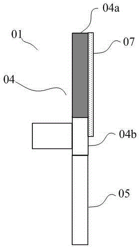
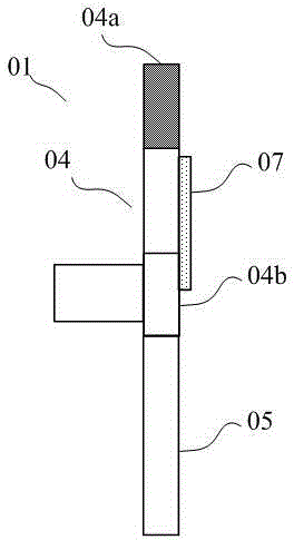
[0039] The present invention aims to provide a wavelength conversion device, such as figure 2 As shown, the wavelength conversion device 01 includes a motor 02, and the motor 02 drives a substrate 03, which is usually in the shape of a disc, rotates periodically, and receives laser irradiation. Wherein, the substrate 03 includes a non-transmissive area 04 and a transmissive area 05, and the non-transmissive area and the transmissive area form a disk-shaped wheel surface. That is to say, the names of the above-mentioned partitions mentioned in other embodiments of the present invention also have the same meaning as the embodiments of the present invention. Wherein, the substrate 03 is made of a transparent material, such as transparent glass, capable of transmitting light, including infrared light. The transmission area 05 is made of a transparent material, usually transparent glass, for transmitting the incident laser light.
[0040] see Figure 3A and Figure 3B, the non...
Embodiment 2
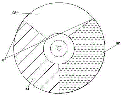
[0058] The same parts and similar principle derivations in this embodiment of the present invention and Embodiment 1 will not be repeated here. The difference is that in this embodiment, as Figure 8A As shown, the fluorescent region 04a is a fluorescent partition of one color, specifically including the green fluorescent region 41, and the transmissive region 05 is used to transmit blue laser light. or as Figure 8B As shown, the fluorescent region 04a is a green fluorescent region 41, and the transmissive region 05 includes a transmissive region 51 and a transmissive region 52, which are used to transmit blue laser light and red laser light respectively. In this specific embodiment, the provided wavelength conversion device receives Two kinds of blue and red lasers are incident, and correspondingly, the incident laser light source is a two-color laser light source.
[0059]Similarly, the reflective film is disposed on the fan-shaped area where the green fluorescent region 4...
Embodiment 3
[0063] Embodiment 3 of the present invention proposes a wavelength conversion device 11, such as Figure 10 As shown, the difference from Embodiment 1 and Embodiment 2 is that the sensor 06 in the embodiment of the present invention is a group of sensors, including a sending sensor 61 and a receiving sensor 62, which are respectively located on both sides of the wavelength conversion device, specifically , see Figure 10 , the transmitting sensor 61 is located on the light-incident side of the wavelength conversion device 11 , and the receiving sensor 62 is located on the light-emitting side of the wavelength conversion device 11 .
[0064] Assuming that the setting of the reflective film in the embodiment of the present invention is as follows Figure 4B As shown, it is a circular ring area located within the range of the fluorescent area 14 .
[0065] Based on the above settings, the working process of the wavelength conversion device is as follows:
[0066] When the send...
PUM
 Abstract
Description
Claims
Application Information
 - R&D
- Intellectual Property
- Life Sciences
- Materials
- Tech Scout
- Unparalleled Data Quality
- Higher Quality Content
- 60% Fewer Hallucinations
Browse by: Latest US Patents, China's latest patents, Technical Efficacy Thesaurus, Application Domain, Technology Topic, Popular Technical Reports.
© 2025 PatSnap. All rights reserved.Legal|Privacy policy|Modern Slavery Act Transparency Statement|Sitemap|About US| Contact US: help@patsnap.com