Fault mode thrust allocation method for geostationary orbit satellite electric thruster

A technology of geostationary orbit and thrust distribution, applied in the field of spacecraft control, can solve the problems of large fuel consumption, large amount of calculation, no optimization solution and no effective solutions.

Active Publication Date: 2016-02-24
BEIJING INST OF CONTROL ENG
View PDF2 Cites 22 Cited by
  • Summary
  • Abstract
  • Description
  • Claims
  • Application Information

AI Technical Summary

Problems solved by technology

However, as far as its introduction is concerned, there are mainly problems such as uncertain ignition position, insufficient consideration of orbit control constraints, and high fuel consumption.
Other strategies focus on establishing an overall trajectory control model, and then use numerical optimization methods to solve the control parameters. These methods usually take the least fue

Method used


Image

  • Fault mode thrust allocation method for geostationary orbit satellite electric thruster
  • Fault mode thrust allocation method for geostationary orbit satellite electric thruster
  • Fault mode thrust allocation method for geostationary orbit satellite electric thruster

Examples


specific Embodiment approach

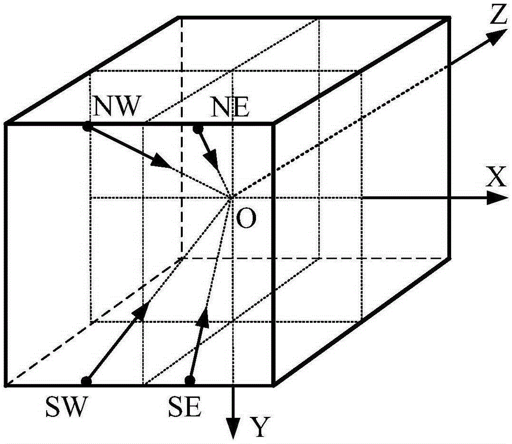
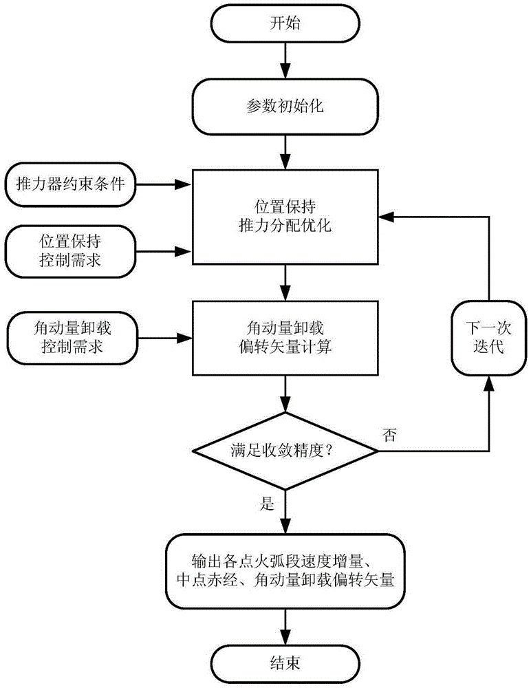
[0053] The invention provides a thrust distribution method suitable for position protection and angular momentum unloading under the fault condition of an electric propulsion GEO satellite thruster, and satisfies engineering constraints such as control performance indicators, fuel consumption, and energy constraints. The equipment on which the method relies includes electric propulsion GEO satellites and electric thrusters installed on the satellites, on-board computers, attitude control systems and other auxiliary equipment. The specific implementation is as follows:

[0054] 1) Determine thrust distribution input conditions

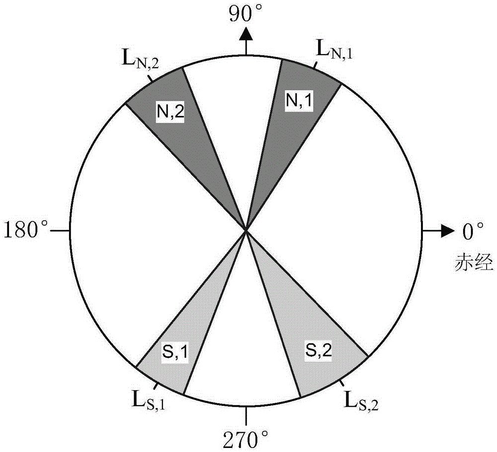
[0055] 11) Ignition position constraint

[0056] Determine the allowable range L of right ascension for ignition according to the orbital illumination conditions, energy conditions on the planet, and working conditions of the electric thruster ava ;

[0057] 12) Ignition speed increment constraints

[0058] According to the limitation of the thruste...

Embodiment

[0093] Satellite characteristics refer to the current mainstream electric propulsion GEO communication satellite platform data, and the characteristic parameters are shown in Table 1:

[0094] Table 1 Characteristic parameters of electric propulsion GEO satellites

[0095]

[0096]

[0097] The thruster ignition speed increment calculated by optimization iteration is as follows: Figure 4 , the phase distribution of the midpoint of the ignition arc is as follows Figure 5 . In each control cycle, the two thrusters are ignited four times, and the ignition parameters are obtained by solving the above algorithm, and there is no unsolvable situation.

[0098] Figure 6 is the time history of the eccentricity vector, under the action of the position protection control, the eccentricity remains stable, and the size does not exceed 2×10 -4 .

[0099] Figure 7 is the time history of the inclination vector. Under the action of position protection control, the inclination v...


PUM


Abstract

The invention belongs to the field of spacecraft control, and relates to a fault mode thrust allocation method for a geostationary orbit satellite electric thruster. The method comprises the steps of firstly, determining a thrust allocation input condition, including ignition position constraint, ignition velocity increment constraint and orbit control demand; secondly, allocating and optimizing position keeping thrust, establishing an electric thruster pointing model, selecting a thruster, defining ignition parameters, and optimizing and calculating the ignition parameters; and finally, calculating an angular momentum unloading deflecting vector. Aiming at the problem of high fuel consumption in a traditional definitive solution mode, a nonlinear hybrid constraint optimization model is established, and key parameters such as time length of each thrust ignition arc, ignition position and the like are solved by taking fuel optimization as a target, so that the method can realize fuel optimization under engineering constraints.

Description

technical field [0001] The invention relates to a method for distributing thrust in fault mode of an electric thruster of a geostationary orbit satellite, and belongs to the field of spacecraft control. Background technique [0002] Space electric propulsion technology is an important way to improve the energy utilization efficiency and orbit control performance of spacecraft. In recent years, with the improvement of indicators such as on-orbit life and load / platform weight ratio, a large number of high-orbit satellites at home and abroad have adopted electric propulsion technology. the trend of. As my country's next-generation large-capacity / high-performance geostationary orbit (GEO) communication satellite platform, Dongfanghong-5 satellite platform (DFH-5 platform) and all-electric push satellite platform (DFH-4SP) based on electric propulsion have entered the engineering development stage. [0003] Compared with traditional chemical propulsion methods, electric propulsi...

Claims


Application Information

Patent Timeline
IPC IPC(8): G05B13/04
CPCG05B13/04
Inventor 石恒陈守磊汤亮韩冬胡少春马雪
Owner BEIJING INST OF CONTROL ENG
Why Eureka
Try Eureka